English (GB)
8
6.5 Outdoor installation
If you install the motor outdoors, provide the motor
with a suitable cover and open the drain holes to
avoid condensation on the electronic components.
See figures 4 and 5.
The cover must be sufficiently large to ensure that
the motor is not exposed to direct sunlight, rain or
snow. Grundfos does not supply covers. We
therefore recommend that you have a cover built for
the specific application. In areas with high humidity,
we recommend that you connect the motor
permanently to the mains supply and activate the
built-in standstill heating function. See section
10.19 ""Standstill heating"".
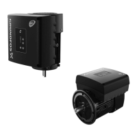
Fig. 4 Examples of covers (not supplied by
Grundfos)
6.6 Drain holes
If you install the motor in moist surroundings or areas
with high humidity, the bottom drain hole must be
open. The enclosure class of the motor will then be
lower. This helps prevent condensation in the motor
as the motor becomes self-venting, and it allows
water and humid air to escape.
The motor has a plugged drain hole on the drive
side. You can turn the flange 90 ° to both sides or
180 °.
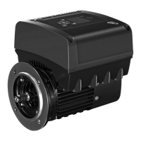
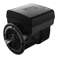
Fig. 5 Drain holes
7. Electrical installation
If the power supply cable is damaged, it must be
replaced by the manufacturer, the manufacturer's
service partner or a similarly qualified person.
The user or the installer is responsible for the
installation of correct earthing and protection
according to local regulations. All operations must be
carried out by a qualified electrician.
7.1 Protection against electric shock,
indirect contact
Protective-earth conductors must always have a
yellow and green (PE) or yellow, green and blue
(PEN) colour marking.
7.1.1 Protection against mains voltage transients
The motor is protected against mains voltage
transients in accordance with EN 61800-3.
7.1.2 Motor protection
The motor requires no external motor protection. The
motor incorporates thermal protection against slow
overloading and blocking.
7.1.3 External switch
We recommend that you connect the motor to an
external switch.
Connect the switch via the terminals 2 (DI1) and 6
(GND). See fig. 10 (FM 100), fig. 11 (FM 200) or fig.
12 (FM 300).
Enable the ""External stop"" function. See section
10.7 "Digital inputs".
When fitting a cover to the motor, observe
the guideline in section 6.4 Ensuring motor
cooling.
TM05 3496 3512TM02 9037 1604
DANGER
Electric shock
- Death or serious personal injury
- Switch off the power supply to the motor
and to the signal relays. Wait at least 5
minutes before you make any
connections in the terminal box. Make
sure that the power supply cannot be
accidentally switched on.
DANGER
Electric shock
- Death or serious personal injury
- Check that the supply voltage and
frequency correspond to the values
stated on the nameplate.
WARNING
Electric shock
- Death or serious personal injury
- Connect the motor to protective earth
and provide protection against indirect
contact in accordance with local
regulations.

 Loading...


