English (GB)
35
10.8 ""Digital inputs/outputs""
Available inputs and outputs depend on the
functional module fitted in the motor. See section
15. Identification of functional module.
You can select if the interface is to be used as input
or output. The output is an open collector and you
can connect it to e.g. an external relay or controller
such as a PLC etc.
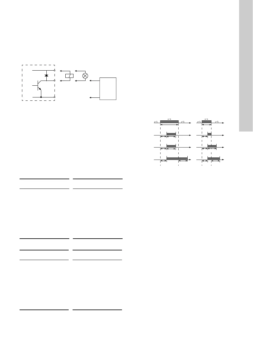
Fig. 31 Example of configurable digital
inputs/outputs
To set a digital input/output, make the settings below.
Mode
You can set the digital input/output 3 and 4 to act as
digital input or digital output.
Function
You can set the digital input/output 3 and 4 to the
functions stated in the tables below. See also
sections 10.7 "Digital inputs" and 10.9 "Signal relay"
(""Relay outputs"").
Possible functions, digital input/output 3
Possible functions, digital input/output 4
Activation delay (only for input)
Select the activation delay (T1).
It is the time between the digital signal and the
activation of the selected function.
Range: 0-6000 seconds.
Duration timer mode (only for input)
Select the duration timer mode. See fig. 30.
• ""Not active""
• active with interrupt (mode A)
• active without interrupt (mode B)
• active with after-run (mode C)
Select the duration time (T2).
It is the time which, together with the mode,
determines how long the selected function is active.
Range: 0-15,000 seconds.
Fig. 32 Duration timer function of digital inputs
TM06 4463 2315
"Function if input" "Function if output"
• ""Not active""
• ""External stop""
•""Min.""
•""Max.""
• ""External fault""
• ""Alarm resetting""
• Reverse rotation
• ""Predefined
setpoint digit 2""
• ""Not active""
• ""Ready""
•""Alarm""
• ""Operation""
• ""Warning""
• ""Limit 1 exceeded""
• ""Limit 2 exceeded""
"Function if input" "Function if output"
• ""Not active""
• ""External stop""
•""Min.""
•""Max.""
• ""External fault""
• ""Alarm resetting""
• Reverse rotation
• ""Predefined
setpoint digit 3""
• ""Not active""
• ""Ready""
• ""Alarm""
• ""Operation""
• ""Warning""
• ""Limit 1 exceeded""
• ""Limit 2 exceeded""
TM06 4949 3415
T input
T input > T1 + T2 T input < T1 + T2
T1 T2
T1 T2
T1 T1 T2T2
T1
T1
T input
T2
Mode C
Mode B
Mode A
Digital
input
T input > T1 + T2
T input < T1 + T2
 Loading...