19
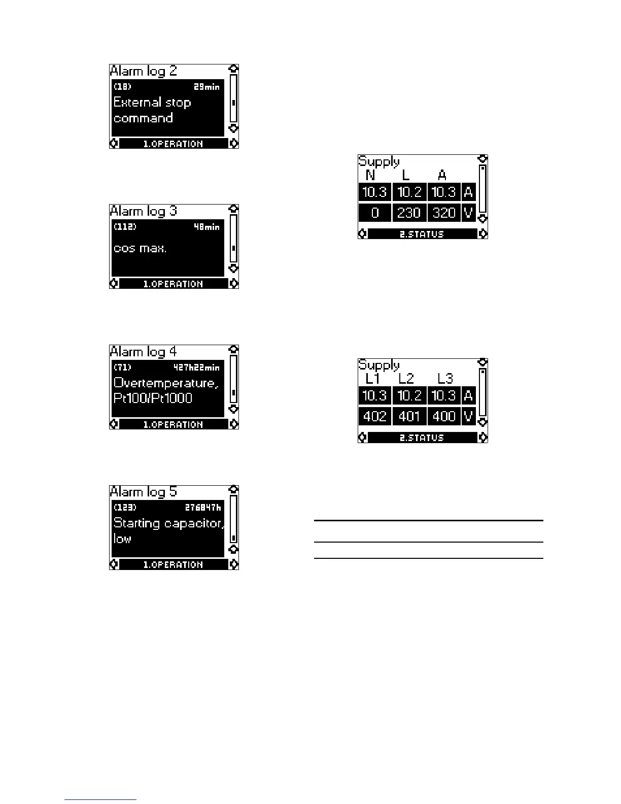
9.1.6 Alarm log 2
For a list of trip and warning codes, see section 16.
9.1.7 Alarm log 3
For a list of trip and warning codes, see section 16.
9.1.8 Alarm log 4
For a list of trip and warning codes, see section 16.
9.1.9 Alarm log 5
For a list of trip and warning codes, see section 16.
9.2 Menu 2. STATUS
The displays appearing in this menu are status dis-
plays only, i.e. actual operating data. It is not possi-
ble to change values. For measuring accuracies, see
section 15.4.
When [OK] is pressed continuously, the displayed
value is updated.
9.2.1 Supply overview
Example of a single-phase current and voltage
measurement.
When a single-phase motor is connected correctly,
the "N" shows 0 V.
The MP 204 measures the phase voltage as well as
the voltage across the auxiliary winding. The current
value is the actual phase current and the current
through the auxiliary winding.
Example of a three-phase current and voltage meas-
urement.
The MP 204 measures all mains voltages and cur-
rents.
The voltage is indicated as follows:
The currents are actual values measured through the
I1, I2, I3.
L1 L2 L3
U
L1-L2
U
L2-L3
U
L3-L1

 Loading...
