7
6.2 Input for Pt100/Pt1000
See fig. 6, pos. 5.
For examples of Pt100/Pt1000 connection,
see figs. 7 and 8.
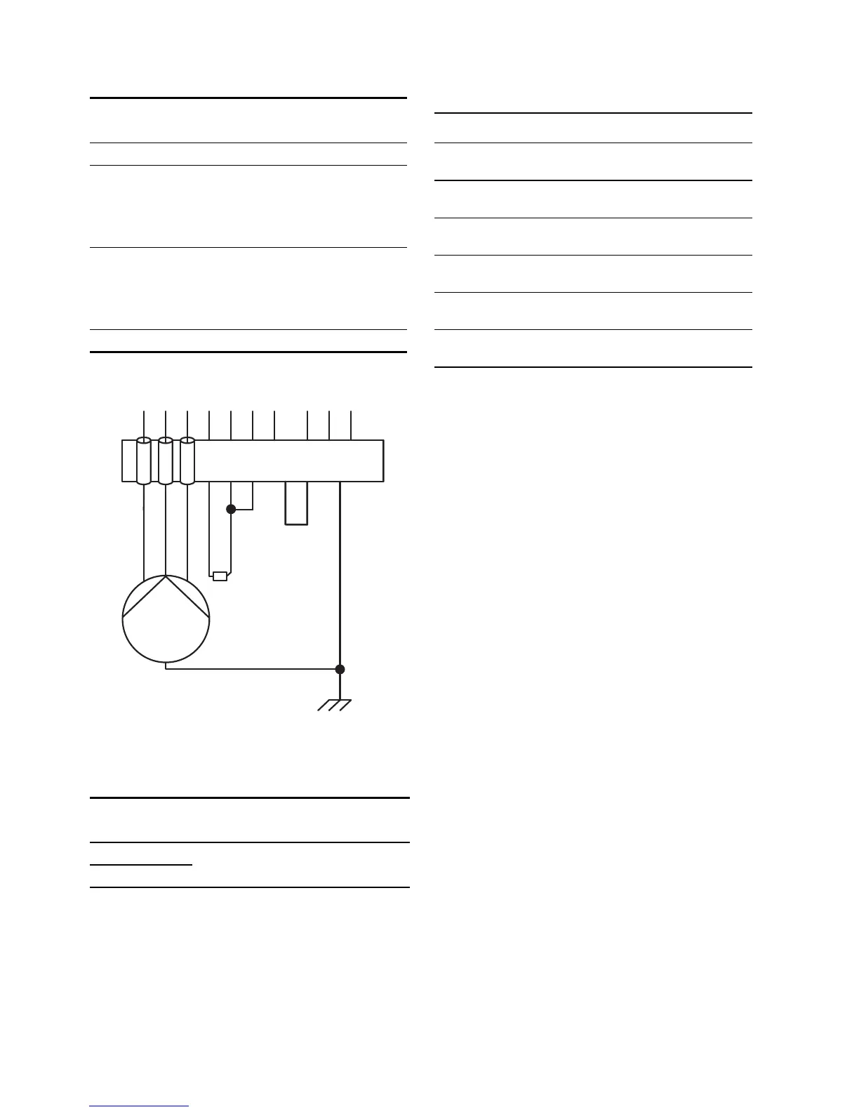
Fig. 7 Two-core Pt100/Pt1000 connection
6.3 Input for PTC/thermal switch
See fig. 6, pos. 3.
If not used, short-circuit the PTC input using a wire,
or deactivate it with the R100. See section 9.4.11.
6.4 Back-up fuses
Maximum back-up fuse sizes which may be used for
the MP 204 appear from the table below:
At motor currents up to and including 120 A, the
cables to the motor can be taken direct through the
I1-I2-I3 of the MP 204.
At motor currents above 120 A, current transformers
must be used. See fig. 5, pos. 1.
Note: If back-up fuses above 50 A are used, the
L1-L2-L3 and "5" to the MP 204 must be protected
separately with max. 10 A fuses. See fig. 8.
If current transformers are used, the L1-L2-L3 and
"5" to the MP 204 must be protected with max. 10 A
fuses.
For installation examples, see figs. 8 to 12.
Terminal
designation
Description
+ Resistance input.
C
Correction for lead resistance.
To be connected by means of a
three-core Pt100/Pt1000 connec-
tion, otherwise the two "C" termi-
nals are to be short-circuited.
C
Correction for lead resistance.
To be connected by means of a
three-core Pt100/Pt1000 connec-
tion, otherwise the two "C" termi-
nals are to be short-circuited.
SH 0 V (screen).
TM03 1397 2205
Terminal
designation
Description
T1
Connection of PTC/thermal switch
T2