12
7. Start-up
A basic setting of the MP 204 can be made on the
control panel.
Additional functions must be set with the R100
remote control.
7.1 Operation
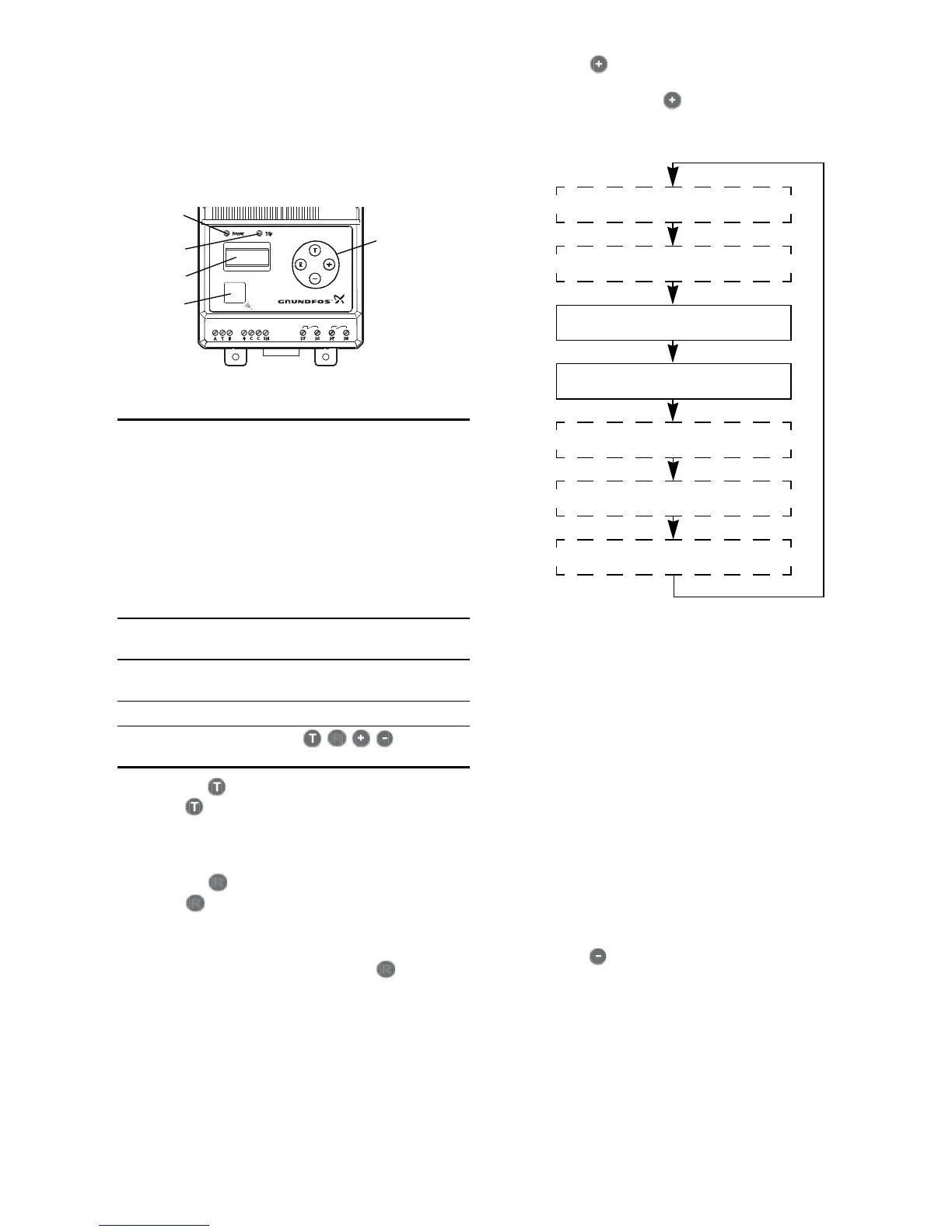
Fig. 14 Control panel
7.1.1 Button (Test)
Press the button to open trip relay connection
95-96 and close signal relay connection 97-98.
The red "Trip" indicator light is on.
The function is identical to the overload trip.
7.1.2 Button (Reset)
Press the button to change the tripped state to
normal state with trip relay connection 95-96 closed
and signal relay connection 97-98 open. The red
"Trip" indicator light is off. This implies that the
tripped state has actually ceased. The button
also resets warnings, if any.
7.1.3 Button
Normally the actual current or temperature appears
in the display. Press the button to show informa-
tion in the display, according to the following
sequence:
Fig. 15 Sequence in display
• The trip code only appears if the MP 204 is
tripped. Switches between "trip" and trip code.
• The warning code only appears if the limit value of
one or more warnings has been exceeded, and if
warning code indication has been activated.
See section 9.4.16.
• Temperatures only appear if the matching sensors
have been connected and activated. If no Temp-
con signal is received, "----" appears in the
MP 204 display.
•Cos ϕ only appears if this indication has been acti-
vated with the R100. See section 9.4.16.
When the motor is operating, the display shows the
actual value.
When the motor stops, the display shows the last
measured value.
7.1.4 Button
Only used in connection with the basic setting of the
MP 204.
TM03 0181 4404
Pos. 1
"Power"
indicator light
• Flashes green until
the MP 204 is ready
for operation (power-
on delay, see sec-
tion 9.4.5).
• Is permanently green
when the MP 204 is
ready for operation.
• Flashes red when
communicating with
the R100.
Pos. 2
"Trip" indicator
light
Is red when the trip re-
lay is activated.
Pos. 3 Display
4 digits, for basic set-
ting and data reading.
Pos. 4 IR field R100 communication.
Pos. 5
Operating
buttons
Setting and operation.