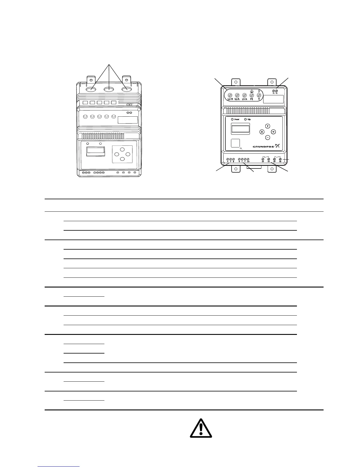
Pos. Designation Three-phase connection Single-phase connection Cable
1
I1 Entry for phase L1 to motor Entry for neutral
Max.
ø16
mm
I2 Entry for phase L2 to motor Entry for phase
I3 Entry for phase L3 to motor Entry for auxiliary winding
2
L1/N Supply: L1 Supply: Neutral
Max.
6
1)
mm
2
L2/L Supply: L2 Supply: Phase
L3/A Supply: L3 Auxiliary winding
FE Functional earth
5 Insulation measurement
3
T1
PTC/thermal switch
Max.
2.5
2)
mm
2
T2
4
A GENIbus data A
Y Reference/screen
B GENIbus data B
5
+
Pt100/Pt1000 sensorC
C
SH Screen
6
95
Trip relay NC
96
7
97
Signal relay NO
98
UL requirement:
For field wiring terminals, min. 60/75°C
stranded copper conductors must be used.