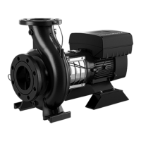
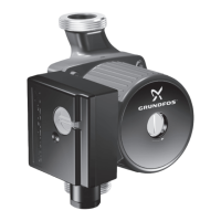
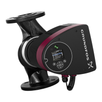
5.2 Installation positions
Arrows on the pump housing show the direction of liquid flow
through the pump.
The pumps can be installed with the motor and pump shaft in all
positions between vertical and horizontal, but the motor must never
fall below the horizontal plane.
Horizontal motors with feet must always be supported.
TM085812
Installation positions
A: 0.33 - 50 hp (0.25 - 37 kW)
B: 0.33 - 268 hp (0.25 - 200 kW)
Fit isolating valves on either side of the pump as this makes it
unnecessary to drain the system if the pump needs to be cleaned or
repaired.
5.3 Foundation of NB pump without base frame
Non-compliance may result in functional faults which will
damage the pump components.
Observe the following requirements when preparing the foundation:
• We recommend that you install the pump on a plane and rigid
concrete foundation which is heavy enough to provide
permanent support for the entire pump.
• The foundation must be capable of absorbing any vibration,
normal strain or shock.
• Optimally, the weight of the concrete foundation should be at
least 1.5 times the weight of the pump.
• The concrete foundation must have an absolutely level and
even surface.
• The foundation length and width must always be 8 inches (200
mm) larger than the length and width of the pump. See the
figure below.
TM085813
Foundation
• The minimum height of the foundation, indicated by h
f
, can then
be calculated with the following formula:
h
f
=
m
pump
× 1.5
L
f
× B
f
× δ
concrete
h
f
Height of the foundation [in] ([m])
L
f
Length of the foundation [in] ([m])
B
f
Width of the foundation [in] ([m])
m
pump
Mass of the pump [lbs] ([kg])
δ
concrete
Density of the concrete [lb/in
3
] ([kg/m
3
])
The density of concrete, indicated by δ, is usually taken
as 0.08 lb/in
3
(2,200 kg/m
3
)
• In installations where noise-less operation is particularly
important, we recommend a foundation with a mass up to 5
times that of the pump. See also Vibration damping.
15
English (US)

 Loading...


