4 / 17
4. Dismantling and assembly
4.1 General description
If it is necessary to dismantle the PM unit, either because it is choked or damaged, follow the instructions in the
following sections.
Position numbers of parts (digits) refer to drawings and parts lists see section 7. Drawings; position numbers of
tools (letters) refer to section 3. Service tools.
Before dismantling
• Switch off the power supply to the PM unit.
• Disconnect the power supply cable at the connection point.
• Close the isolating valves, if fitted, to avoid draining the piping system.
Before assembly
• Clean and check all parts.
• Replace defective parts by new parts.
• Order the necessary service kits.
• Always replace gaskets and O-rings when the PM unit is serviced.
During assembly
• Lubricate and tighten screws and nuts to the correct torque. See section 2. Torques and lubricants.
4.2 PM 1
4.2.1 Removing the supply cables
1. Remove screws (pos. 1), and take off front cover (pos. 2).
2. Remove terminal board cover (pos. 3).
3. Disconnect cables (pos. 9 and 10) from the terminals on the electronic unit (pos. 4).
4. Loosen cable entries (pos. 11), and pull cables (pos. 9 and 10) out of the cable entries.
4.2.2 Fitting the supply cables
1. Lead cables (pos. 9 and 10) into the cable entries (pos. 11), and tighten them.
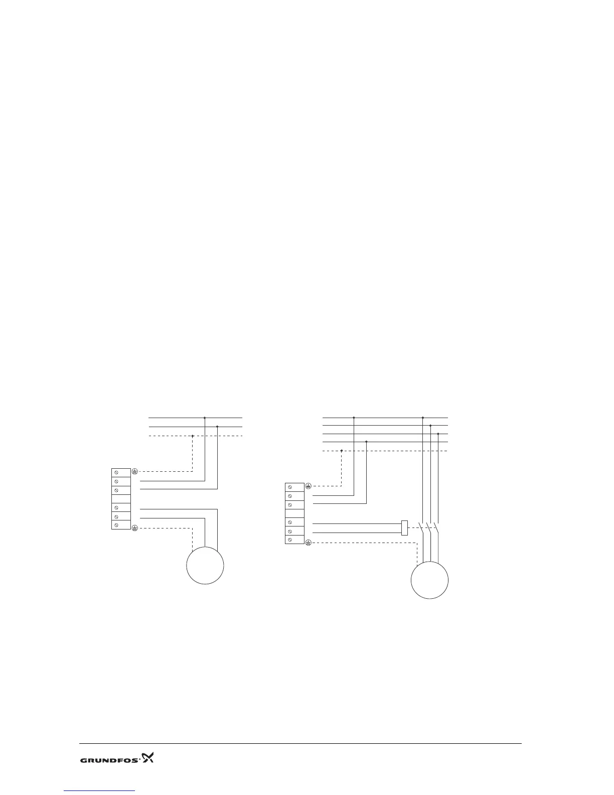
Fig. 1 Connecting cables to single- and three-phase motors
2. Connect cables (pos. 9 and 10) to the terminals in the electronic unit (pos. 4).
3. Fit terminal board cover (pos. 3).
4. Fit front cover (pos. 2), and fit and cross-tighten screws (pos. 1).
TM03 9220 3707
TM04 1953 1508
 Loading...