Pos. Description
Y&G Yellow and green
N/A (Not used)
A Standard version with thermal switches
B Sensor version with thermal switch, Pt1000, moisture switch and WIO sensor
C Sensor version with thermal switch, PTC thermistor*, moisture switch and WIO sensor
*Pumps with 4 kW and larger motors sold in Australia or New Zealand are fitted with a PTC thermistor.
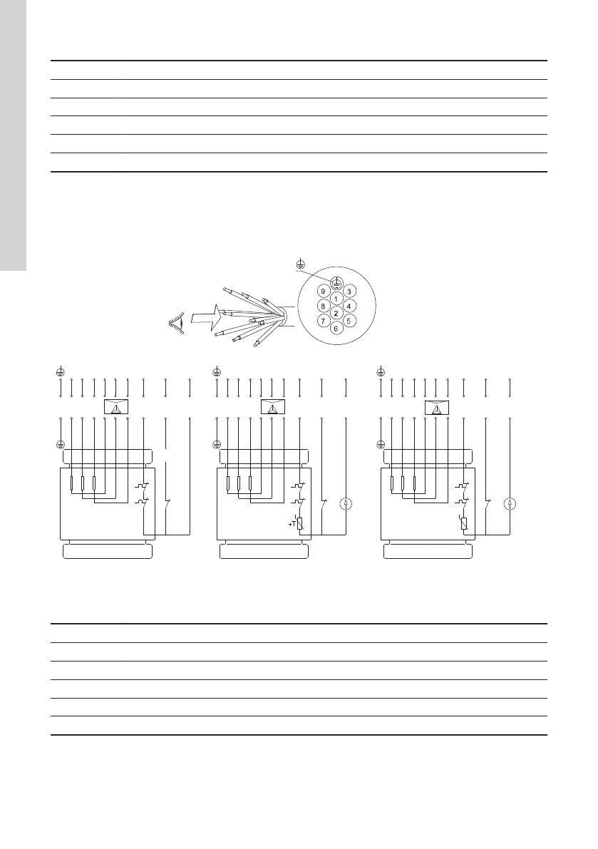
10-core cable
The figures below show the wiring diagrams for SE1, SEV pumps with 10-core cable in three versions, one
without sensors and two with WIO sensor and moisture switch.
L1
L2 L3 L2
L3 L1 T1 T2
T3
U1
V1
W1
U2
V2 W2
1
3
5
4
6
2
7
8
9
1
3
5
4
6
2
7
8
9
1
3
5
4
6
2
7
8
9
M
WIO
M
WIO
N/A
A B C
Y&G
P1
P2
P5
L1 L2
L3 L2
L3 L1
P1
P2
P5
L1
L2 L3 L2
L3 L1
U1
V1
W1
U2
V2
W2
U1
V1
W1
U2
V2 W2
TM046885
Wiring diagram, 10-core cable, star/delta (Y/D)
Pos. Description
Y&G Yellow and green
N/A Sensor version with thermal switch, PTC thermistor*, moisture switch and WIO sensor
A Standard version with thermal switches
B Sensor version with thermal switch, Pt1000, moisture switch and WIO sensor
C Sensor version with thermal switch, PTC thermistor*, moisture switch and WIO sensor
*Pumps with 4 kW and larger motors sold in Australia or New Zealand are fitted with a PTC thermistor.
22
English (GB)
 Loading...