English (GB)
10
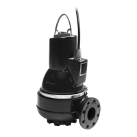
2.1 Product drawing
Fig. 1 SL1 pump
2.2 Control and monitoring
The pumps can be controlled via the Grundfos controllers
LC, LCD 107, LC, LCD 108, LC, LCD 110.
Pumps with sensor are supplied together with an IO 111 which
can receive signals from the following transmitters:
• water-in-oil-sensor (WIO sensor) in the pump
• moisture sensor in the motor
• temperature sensor in the stator windings
• winding resistance sensor in the motor.
For further information, see installation and operating instructions
for the specific sensor.
2.3 Applications
SL1 and SLV pumps are designed for pumping these liquids:
• large quantities of drainage and surface water
• domestic wastewater with discharge from toilets
• wastewater with a high content of fibres
(SuperVortex impeller)
• municipal and commercial sewage and wastewater.
SL1 and SLV pumps are ideal for installation in locations such as:
• public buildings
• blocks of flats
• industries
• garages
• multi-storey car parks
• vehicle washing tunnels
• restaurants.
The compact design makes the pumps suitable for both
temporary and permanent installation.
2.4 Pump selection
The table below shows which pump version to select for a
number of liquids:
Impeller type: 1 = S-tube impeller, V = SuperVortex impeller.
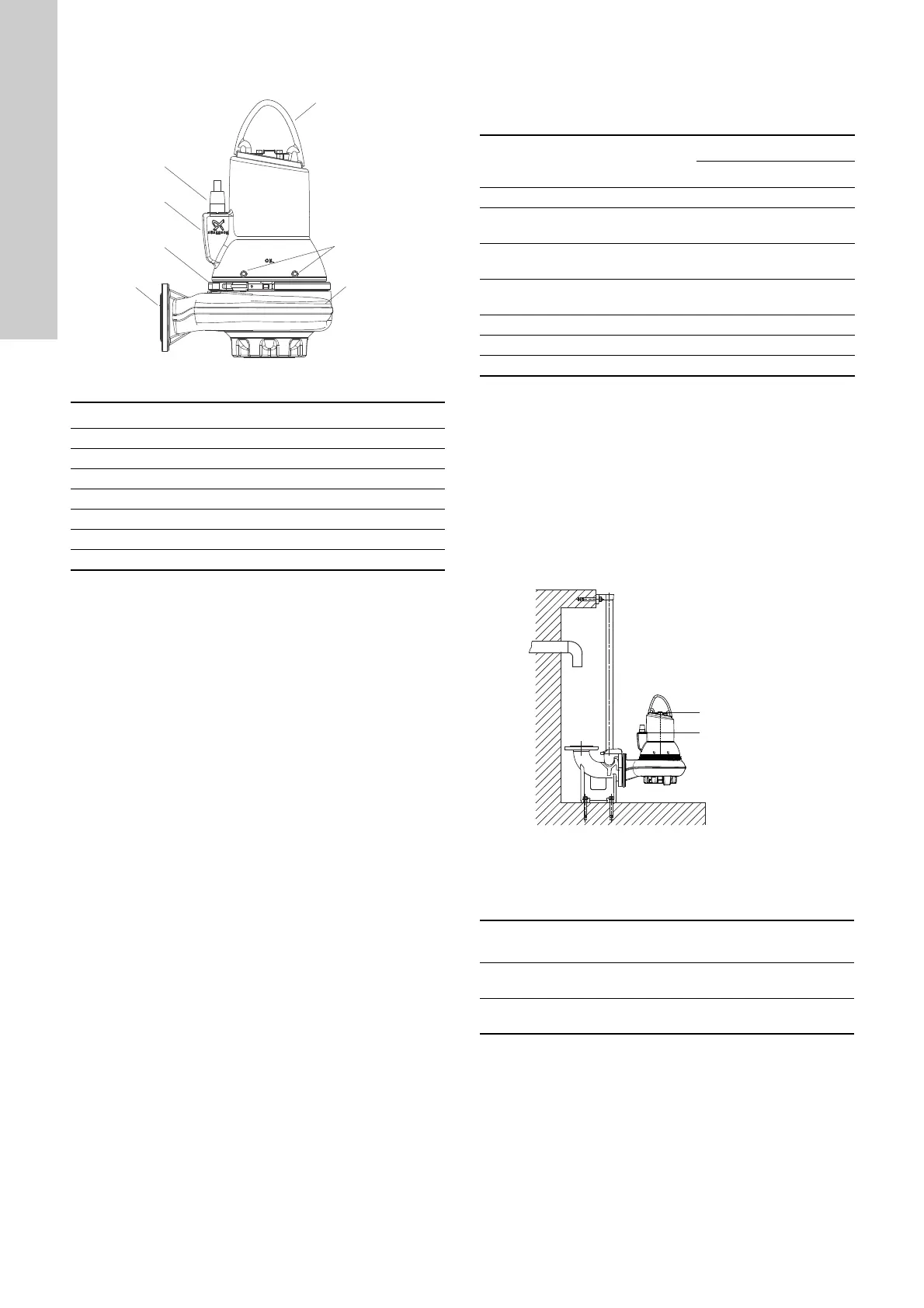
2.5 Operating conditions
The Grundfos SL1 and SLV pumps are suitable for the following
operating situations:
• S1 operation (continuous operation), the pump must always
be covered by the pumped liquid to the top of the motor.
See fig. 2.
• S3 operation (intermittent operation), the pump must always
be covered by the pumped liquid up to the top of the cable
entry. See fig. 2.
For further information about S1 and S3 operation, see section
9.2 Operating modes.
Fig. 2 Stop levels
pH value
SL1 and SLV pumps in permanent installations can be used for
pumping liquids with the following pH values:
1)
For fluctuating pH values, the range is pH 4 to 14.
TM04 2648 2808
Pos. Description
1 Lifting bracket
2Nameplate
3 Oil screws
4 Discharge flange
5 Cable plug
6Clamp
7 Pump housing
Pumped liquid
Pump passage [mm]
50 65 80 100
Drainage water 1 V 1 / V 1 / V
Domestic wastewater without
discharge from toilets
1 V 1 / V 1 / V
Domestic wastewater with
discharge from toilets
1 / V 1 / V
Wastewater with a high content of
fibres
VVV
Industrial wastewater 1 / V 1 / V
Wastewater with gaseous sludge 1 / V 1 / V
Municipal wastewater 1 / V 1 / V
TM04 2649 2808
Pump
type
Material
variant
Material pH value
SL1/SLV Standard
Cast iron impeller and pump
housing
6.5 to 14
1)
SLV Q
Stainless steel impeller and
cast iron pump housing
6 to 14
1)

 Loading...