English (GB)
22
8.6.1 Technical data
For further information, see installation and operating instructions
for IO 111.
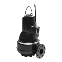
8.7 IO 113
IO 113 provides an interface between a Grundfos wastewater
pump equipped with sensors and the pump controller(s).
The most important sensor status information is indicated on the
front panel.
One pump can be connected to one IO 113 module.
Together with the sensors, the IO 113 provides a galvanic
isolation between the motor voltage in the pump and the
connected controller(s).
IO 113 can do the following as standard:
• Protect the pump against overheating.
• Monitor the status of these items:
– motor winding temperature
– leakage (WIO/WIA)
– moisture in pump.
• Measure the stator insulation resistance.
• Stop the pump in case of alarm.
• Remotely monitor the pump via RS-485 communication
(Modbus or GENIbus).
• Control the pump via a frequency converter.
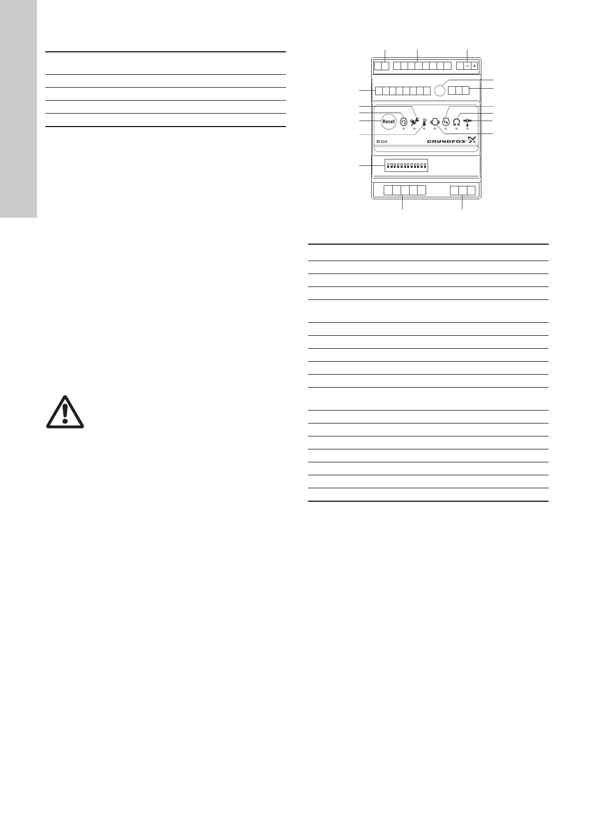
Fig. 13 IO 113 module
Supply voltage:
24 VAC - 10 %/+ 10 %, 50 and 60 Hz
24 VDC - 10 %/+ 10 %
Input current: Min. 0.5 A; max. 8 A
Power input: Max. 5 W
Ambient temperature: -25 °C to +65 °C
Enclosure class: IP20
Warning
The IO 113 must not be used for purposes other
than those specified above.
TM05 1881 3811
Pos. Description
1 Terminals for alarm relay
2 Terminals for analog and digital inputs and outputs
3 Terminals for supply voltage
4
Potentiometer for setting the warning limit of stator
insulation resistance
5 Terminals for RS-485 for GENIbus or Modbus
6 Indicator light for moisture measurement
7 Indicator light for stator insulation resistance
8 Indicator light for leakage (WIO/WIA)
9 Indicator light for vibration in pump
10
Terminals for measurement of stator insulation
resistance
11 Terminals for connection of pump sensors
12 DIP switch for configuration
13 Indicator light for motor temperature
14 Button for resetting alarms
15 Indicator light for motor running
16 Indicator light for service
17 Terminals for digital outputs
PET1 T2
G1 A1 G2 A2 K1 K2 R1 R2
D1 D2 D3 D4 D5 D6 D7 D8
P1 P2 P3 P4 P5
AYB
I1 I2 I3
ON DIP
12345678910
11 12
12 3
4
5
6
7
8
9

 Loading...