19
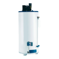
(A) 510 Computer board
Easy-Link system
“Online” LED
Left bank of
DIPswitches
7-Seg. LED
Right bank of
DIPswitches
Easy-Link connectors
are next to the
computer board.
To change the DIPswitch settings for the Easy-Link system,
locate the bank of DIPswitches to the right of the 7-seg LED.
Do not adjust the left bank of DIPswitches.
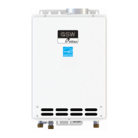
(B) Basic diagram of connections between the Easy-Link
System units.
Communication
cable
Connectors
Right bank of
Dipswitches
OFF
ON
1
2
3
4
5
6
PARENT
1
2
Connectors
Right bank of
Dipswitches
OFF
ON
1
2
3
4
5
6
PARENT
1
2
Connectors
Right bank of
Dipswitches
OFF
ON
1
2
3
4
5
6
PARENT
1
2
Connectors
Right bank of
Dipswitches
OFF
ON
1
2
3
4
5
6
PARENT
1
2
PARENT
unit
CHILD-1
unit
CHILD-2
unit
CHILD-3
unit
CAUTION
The dark squares indicate the direction the
DIPswitches should be set to.
Note:
A remote controller is not required for the Easy-Link
system.
If running the Easy-Link system without a remote control-
ler, please make sure the temperature settings on ALL
the units are set to the same settings. Otherwise, the
units will not operate properly.
If a remote controller is used, the temperature on all the
units in the system will automatically be set to the same
temperature that is set on the remote.
•
•
•
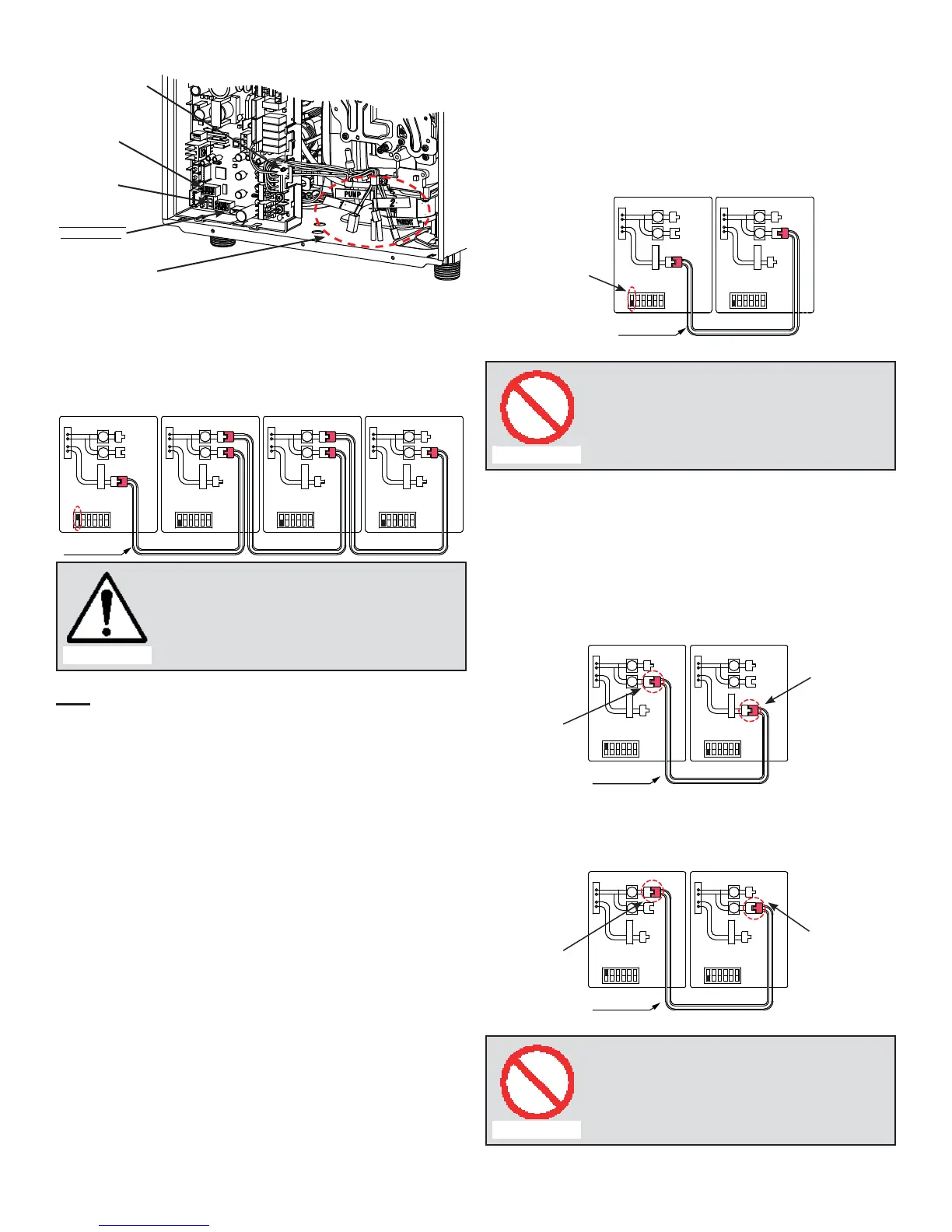
(C) Examples of incorrect settings and/or connections
CASE 1:
Unless you change DIPswitch No. 1 of the “PARENT”
unit to the “ON” position, the system will not work as an
Easy-Link system. The units will operate as individual
units.
Communication
cable
Connectors
Right bank of
Dipswitches
OFF
ON
1
2
3
4
5
6
PARENT
1
2
Connectors
Right bank of
Dipswitches
OFF
ON
1
2
3
4
5
6
PARENT
1
2
PARENT
unit
CHILD-1
unit
Wrong
setting
Prohibited
Wrong DIPswitch setting on the “PARENT”
unit
CASE 2:
If you connect the “1" (or "2") connector of the “PARENT”
unit to the “PARENT" (or "1") connector of the “CHILD-1”
unit, the system will not work as an Easy-link system.
The units will operate as individual units.
Communication
cable
Connectors
Right bank of
Dipswitches
OFF
ON
1
2
3
4
5
6
PARENT
1
2
Connectors
Right bank of
Dipswitches
OFF
ON
1
2
3
4
5
6
PARENT
1
2
PARENT
unit
CHILD-1
unit
Wrong
connection
Wrong
connection
OR
Communication
cable
Connectors
Right bank of
Dipswitches
OFF
ON
1
2
3
4
5
6
PARENT
1
2
Connectors
Right bank of
Dipswitches
OFF
ON
1
2
3
4
5
6
PARENT
1
2
PARENT
unit
CHILD-1
unit
Wrong
connection
Wrong
connection
Prohibited
Wrong connections between the “PARENT”
unit and the “CHILD-1” unit
•
•