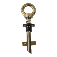
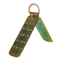
Components and Specifications
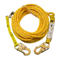
Type A anchorage connector.
Minimum permitted service
temperature: -30° F.
5,000 lb. MBS (minimum
breaking strength).
Materials: zinc-plated steel.
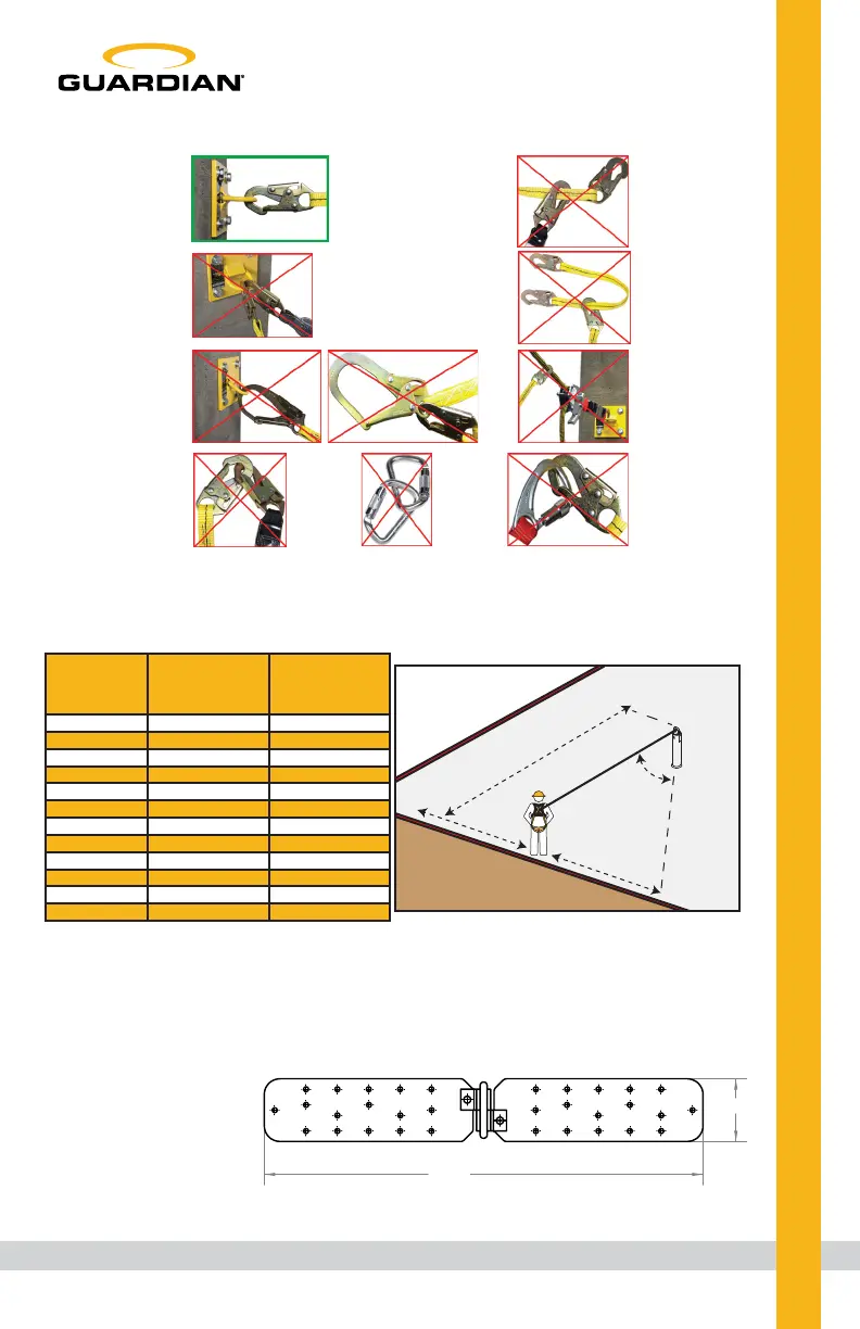
Correct Anchorage Positioning:
This chart details allowable working zones required
to reduce risk of swing falls and improper side loading.
ALWAYS adhere to information specified by chart.
Anchor Distance
From
Leading Edge (Y)
Working Distance
Along Roof Edge
(Either Direction) (X)
Working Angle
From
Perpendicular (Ø)
6’
10’
15’
20’
25’
30’
35’
40’
45’
50’
55’
60’
8’
9’ - 9”
11’ - 7”
13’ - 3”
14’ - 6”
16’
17’ - 2”
18’ - 3”
19’ - 4”
19’ - 10”
21’ - 4”
22’ - 3”
53°
45°
38°
33°
30°
28°
26°
24°
23°
21°
21°
21°
For example, if the anchorage connector is 6’ from the leading
edge (Y), the working distance (X) is 8’ in each direction from
the perpendicular, which translates to a 53° working angle.
Ø: Total Working Angle
X: Working Distance
Along Leading Edge
Y: Distance From
Leading Edge
X
Y
ø
X
Leading Edge
Connector
closed and
locked to
D-ring. OK.
Connector
to integral
lanyard.
NO.
Two or more
snap hooks or
carabiners
connected to
each other. NO.
Two connectors
to same
D-ring. NO.
Connector
directly to
horizontal
lifeline. NO.
Connector
directly to
webbing.
NO.
Incompatible
or irregular
application,
which may
increase risk
of roll-out. NO.
21.00
3.00
3
 Loading...