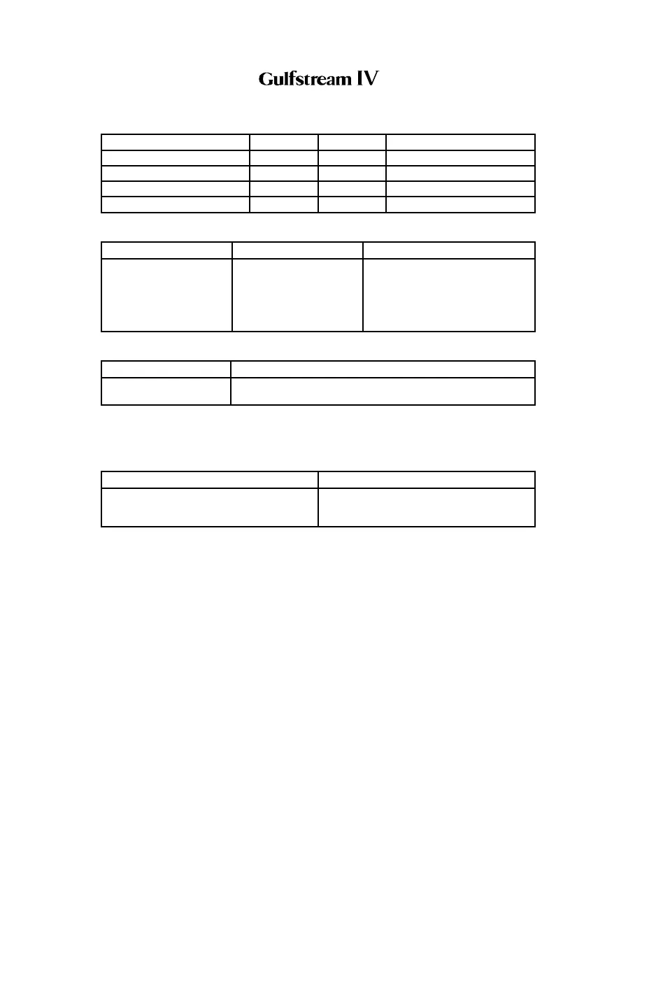
A. Circuit Breakers (CBs):
Circuit Breaker Name: CB Panel: Location: Power Source:
FLAP CONT CPO A-1 Essential DC Bus
FLAP/STAB POS CP E-5 Emergency DC Bus
MANUAL FLAP CONT CPO B-1 Essential DC Bus
SPD BRAKE/FLAP ALARM P D-4 Essential DC Bus
B. Warning (Red) Messages and Annunciations:
CAS Message: SWLP Indication Cause or Meaning:
ACFT
CONFIGURATION
ACFT CONFIG Position of one or more of the
following controls is not correct:
• FLAP Handle
• SPEED BRAKE Handle
• Landing Gear Control Handle
C. Caution (Amber) Messages and Annunciations:
CAS Message: Cause or Meaning:
FLAP ASYMMETRY (1) Flap position asymmetry detected. Flaps have stopped
moving toward selected position.
NOTE(S):
(1) For SPZ-8400 equipped aircraft having ASC 69A (Flap Asymmetry
Indicator Installation).
Annunciation: Cause or Meaning:
FLAP ASYM indicator under FLAP /
STAB position indicator illuminated
amber. (1)
Flap position asymmetry detected. Flaps
have stopped moving toward selected
position.
NOTE(S):
(1) For SPZ-8000 aircraft having ASC 69A (Flap Asymmetry Indicator
Installation).
4. Limitations:
A. Maximum Landing Flaps Extended Operating Altitude:
Maximum operating altitude for extending landing flaps (39°), or flying with
landing flaps extended is 20,000 ft MSL.
B. Flaps Extended Speeds (V
FE /MFE):
(1) Takeoff (10°): 250 KCAS / 0.60 MT
(2) T/O APP (20°): 220 KCAS / 0.60 MT
(3) DOWN (39°):
• 170 KCAS / 0.60 MT — SN 1000 through 1213 without ASC
190
• 180 KCAS / 0.60 MT — SN 1214 and subs, SN 1000 through
1213 with ASC 190
OPERATING MANUAL
PRODUCTION AIRCRAFT SYSTEMS2A-27-00
Page 60
January 31/02
Revision 6