2A-27-70: Spoiler System
1. General Description:
The spoiler system for the Gulfstream IV assists the flight crew in maintaining roll
control of the aircraft, functioning as flight spoilers. Additionally, while in flight, the
spoilers extend to decrease airspeed and increase descent rate, functioning as
speed brakes. On the ground after landing, they function as ground spoilers,
extending to help dump any remaining lift and increase braking effectiveness.
The aircraft has three spoilers on the upper trailing edge of each wing (from
inboard to outboard): a ground spoiler, an inboard flight spoiler and an outboard
flight spoiler. The spoilers are manually and electrically controlled, hydraulically
powered, and mechanically actuated. They are hinged to open forward when
extended and close aft when retracted. Four hydraulic actuators convert hydraulic
pressure to a linear mechanical force to position the spoilers.
Spoiler panel function and position depends upon the control input. Moving the
SPEED BRAKE handle to the extend position extends all six spoiler panels
simultaneously to function as speed brakes. Rotating the control wheel from the
neutral position extends the inboard and outboard spoiler panels on the same
wing as the raised aileron, functioning as flight spoilers to assist with roll control.
When armed, all six spoiler panels extend automatically extend on touchdown to
dump lift and increase braking effectiveness, functioning as ground spoilers.
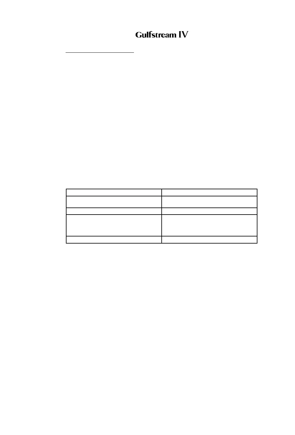
Panel function and position is summarized in the following table:
INPUT CONDITION PANEL POSITION
Maximum Aileron, No Speed Brakes Two Down-Wing Flight Spoilers Extended
23°, All Other Panels Retracted
Maximum Speed Brakes, No Aileron All Six Panels Extended 26°
Maximum Speed Brakes, Maximum
Aileron
Two Down-Wing Flight Spoilers Extended
55°, Two Ground Spoilers Extended 26°,
Two Up-Wing Flight Spoilers Extended
26°,
Automatic Ground Spoilers All Panels Extended 55°
The spoiler system is composed of the following subsystems, units and
components:
• Flight Spoiler System
• Speed Brake System
• Ground Spoiler System
• Flight Power Shutoff System
2. Description of Subsystems, Units and Components:
A. Flight Spoiler System:
(See Figure 25.)
Flight spoilers are incorporated into the roll flight control system to improve
aircraft roll response. Spoiler travel varies in proportion to the degree of roll
input. The flight spoiler system is solely a hydraulically powered system,
thus reversion to manual control is not possible.
As the aileron control system commands an aileron to deflect upward, a
mixing linkage between the aileron and flight spoiler control systems
transmits an extend command to the flight spoiler actuator servo control
valve. The servo control valve then shifts to direct pressure to the flight
OPERATING MANUAL
PRODUCTION AIRCRAFT SYSTEMS 2A-27-00
Page 67
January 31/02
Revision 6