SPEED
SLOW
DISPLAY
VALUE
MODE
L/Q
CIRCUIT
SERIES
MENU
L 1.2345H
Q 0.6789
TESTING
F : 1.000 kHz
V : 1.000 V
AUTO MANU INT.B OFF
R.H OFF
C.V OFF
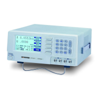
Press F1 key to select the three different measurement
speed. (SLOW, MEDIUM, or FAST)
Figure 4-7. Selection of measurement speed
4-5. Measurement Conditions
4-5-1. Bias Voltage
There are two available bias voltage modes: “Internal” and “External”.
Internal:
An internal DC 2 volts bias voltage will apply to the device under test.
External:
An external DC bias voltage between 0 and 30 volts can be applied to the device
under test. The external bias connection is located on the rear panel. The
maximum current is 200mA. The supply of bias voltage has to be floating, don’t
connect either side to ground. It’s better to wait approximately 1 second for
taking a reading after initiating a testing process, therefore, the device under test
will stabilize after bias voltage applied. The DC bias voltage should be applied
only to capacitors in general. If the DC bias voltage is applied to device of low
impedance, the unreliable testing results will occur.
 Loading...