GETTING STARTED
11
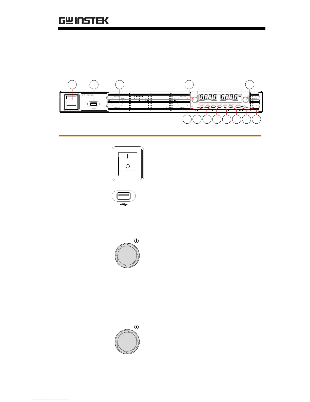
Appearance
PSU Series Front Panel
Lock/Local PROT Function Test Set Output
Unlock ALM_CLR M 1 M 2 M 3
Shift
: Long Push
VSR LAN RMT ERR DLY ALM ISR M 1 M 2 M 3 RUN
C C
A
C V
V
VOLTAGE CURRENT
PSU 40-38
DC Power Supply
0 - 40 V / 0 - 38A
Voltage Current
2 3 4 5
Display Area
1
116 7 8 9 10 12 13
Used to turn the power on/off.
USB A port for data transfer,
loading test scripts etc.
Air inlet for cooling the inside of
the PSU series.
Used to set the voltage value or
select a parameter number in the
Function settings.
The display area shows setting values, output
values and parameter settings. The function LEDs
below show the current status and mode of the
power supply. See page 14 for details.
Used to set the current value or
change the value of a Function
parameter.

 Loading...


