13
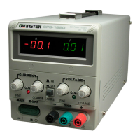
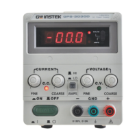
5.PANEL CONTROLS AND INDICATORS
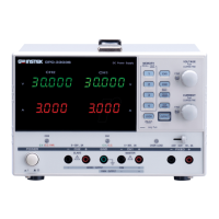
-1.Front panel
(1) CV Indicator Lights when the power is on and in constant voltage operation.
(2) CC Indicator Lights when in constant current operation.
(3) Voltage coarse For the coarse adjustment of the output voltage.
(4) Voltage fine For the fine adjustment of the output voltage.
(5) Current coarse For the coarse adjustment of the output current.
(6) Current fine For the fine adjustment of the output current.
(7) “+” output terminal Positive polarity (Red).
(8) “GND” terminal Earth and chassis ground (Green).
(9)
“–“output terminal
Negative polarity (Black).
(10) Meter Indicates the output voltage.
(11) Meter Indicates the output current.
(12) Power control On/Off switch.
(13) Current HI/LO control Current indicates HI/LO range selection.
5-2.Rear panel
(14) Fuse holder
(15) Power socket.
(16) AC selects switch
With 115V or 230V voltage and current ranges selection (Refer to the
diagrammatic instruction to prevent mis-operating).
(17) Fan Cooling fan.
Artisan Technology Group - Quality Instrumentation ... Guaranteed | (888) 88-SOURCE | www.artisantg.com

 Loading...