2-14
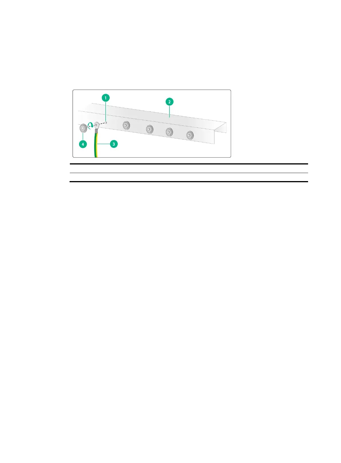
If the grounding cable has a ring terminal, use the ring terminal to connect the grounding cable
to a grounding strip:
a. Remove the hex nut from a ground post on the grounding strip.
b. Attach the ring terminal to the grounding post and use the hex nut to secure the ring terminal
to the grounding post.
Figure2-19 Connecting the grounding cable to a grounding strip
Grounding the switch with a grounding conductor buried in
the earth ground
If the installation site does not have grounding strips, but earth ground is available, hammer a 2.5 m
(8.20 ft) or longer angle iron or steel tube into the earth ground to act as a grounding conductor. Make
sure a minimum of 0.7 m (2.30 ft) is left between the top of the grounding conductor and the ground.
In cold areas, bury the grounding conductor below the frozen soil layer. In areas with thin soil or rocky
gravel, determine the depth for burying the grounding conductor based on the actual condition.
If zinc-coated steel is used, the following dimensions requirements must be met:
Angle iron—A minimum of 50 × 50 × 5 mm (1.97 × 1.97 × 0.20 in).
Steel tube—A minimum of 3.5 mm (0.14 in) in thickness.
Flat steel—A minimum of 40 × 4 mm (1.57 × 0.16 in).
Round steel—A minimum of 10 mm (0.39 in).
Weld the yellow-green grounding cable to the angel iron or steel tube and treat the joint for corrosion
protection.

 Loading...