2-8
2. Make sure the front mounting brackets and shoulder screws are securely attached to the two
sides of the switch.
3. Attach cage nuts to the front rack posts. Make sure the corresponding cage nuts on the left
and right front rack posts are at the same height.
4. One person supports the chassis bottom with one hand, holds the front part of the chassis with
the other, and pushes the chassis into the rack gently. Make sure the shoulder screws rest
firmly on the upper edge of the rear mounting brackets. See Figure2-11 and Figure2-12.
5. The other person attaches the front mounting brackets by using M6 screws and cage nuts to
the front rack posts. Make sure the switch is installed securely in the rack. See Figure2-11 and
Figure2-12. As a best practice, use a torque of 30 kgf-cm (2.94 Nm) to fasten the M6 screws.
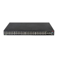
Figure2-11 Mounting the switch in the rack (with the wide flange of the rear mounting
brackets inside the rack)
 Loading...


