4-5
The following subsections describe several H3C recommended IRF connection schemes by using
SFP+ cables and SFP+ transceiver modules and fibers. All these schemes use a ring topology.
In these schemes, all physical IRF ports are located on the same side. If physical IRF ports are on
different sides, you must measure the distance between them to select an appropriate cable.
Connecting the IRF member switches in one rack
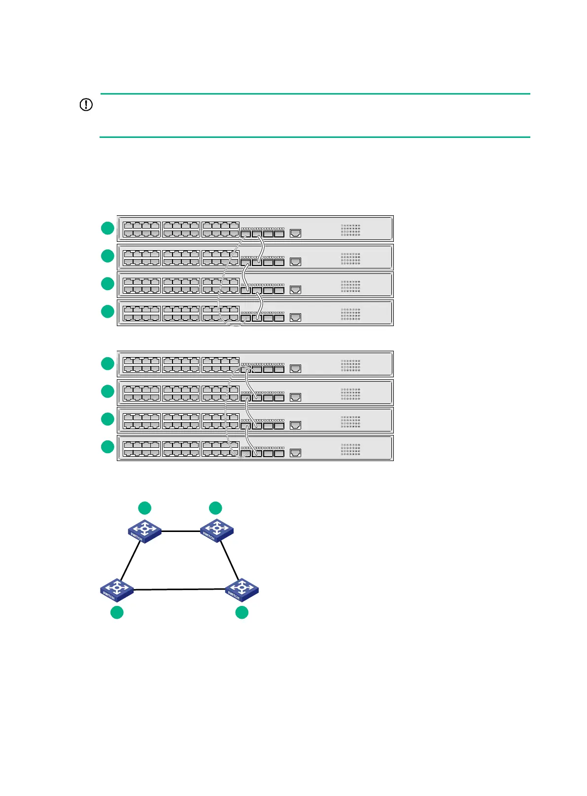
Connect the IRF member switches (4 switches in this example) in a rack as shown in Figure4-4. The
switches in the ring topology (see Figure4-5) are in the same order as connected in the rack.
Figure4-4 Connecting the switches in one rack
Figure4-5 IRF fabric topology

 Loading...


