8
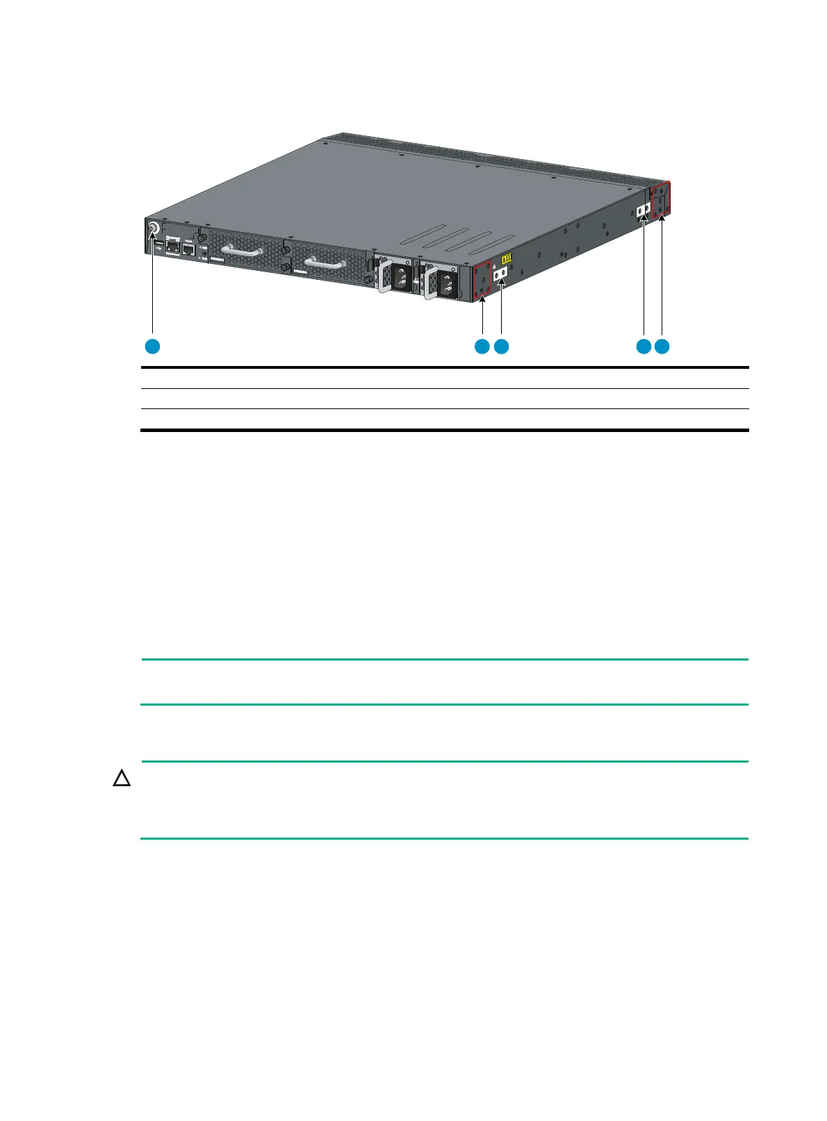
Figure 7 Mounting and grounding positions of the S5820V2-48S/S5820V2-52QF
(LS-5820V2-52QF-H3) /S5820V2-52QF (LS-5820V2-52QF-H5)/S5820V2-54QS-GE
(1) Auxiliary grounding point 2 (2) Rear mounting position
(3) Primary grounding point (4) Auxiliary grounding point 1
(5) Front mounting position
Attaching the mounting brackets and chassis rails to the chassis
1. Align the mounting brackets with the screw holes in the rear mounting position (see Figure 8) or
front mounting position (see Figure 9).
2. Use M4 screws (provided) to attach the mounting brackets to the chassis.
3. Align the chassis rails with the rail mounting holes in the chassis:
{ If the mounting brackets are in the rear mounting position, align the chassis rails with the
screw holes at the front of the side panels (see Figure 8).
{ If the mounting brackets are in the front mounting position, align the chassis rails with the
screw holes at the rear of the side panels (see Figure 9).
4. Use M4 screws (provided) to attach the chassis rails to the chassis.
NOTE:
Secure the mounting brackets and chassis rails to both sides of the chassis in the same way.
Connecting the grounding cable to the chassis
CAUTION:
Select the grounding point as required. The primary grounding point and auxiliary grounding point 1
are located on the left side panel. If you use one of these grounding points, you must connect the
grounding cable to the grounding point before you mount the switch in the rack.
To connect the grounding cable to a chassis grounding point, for example, the primary grounding
point:
1. Choose a grounding point.
2. Unpack the grounding cable and grounding screws.
3. Align the two-hole grounding lug at one end of the cable with the grounding holes of the
grounding point, insert the grounding screws into the holes, and tighten the screws with a
screwdriver to attach the grounding lug to the chassis, as shown in Figure 8.
1
2
3
4 5

 Loading...


