14-25
Step4 Log in to the AP through IE. Launch IE on the Web-based network management terminal (your PC)
and enter the IP address of the management VLAN interface of the AP (here it is http://10.153.17.82).
(Make sure the web-based network management terminal and the AP can reach each other.)
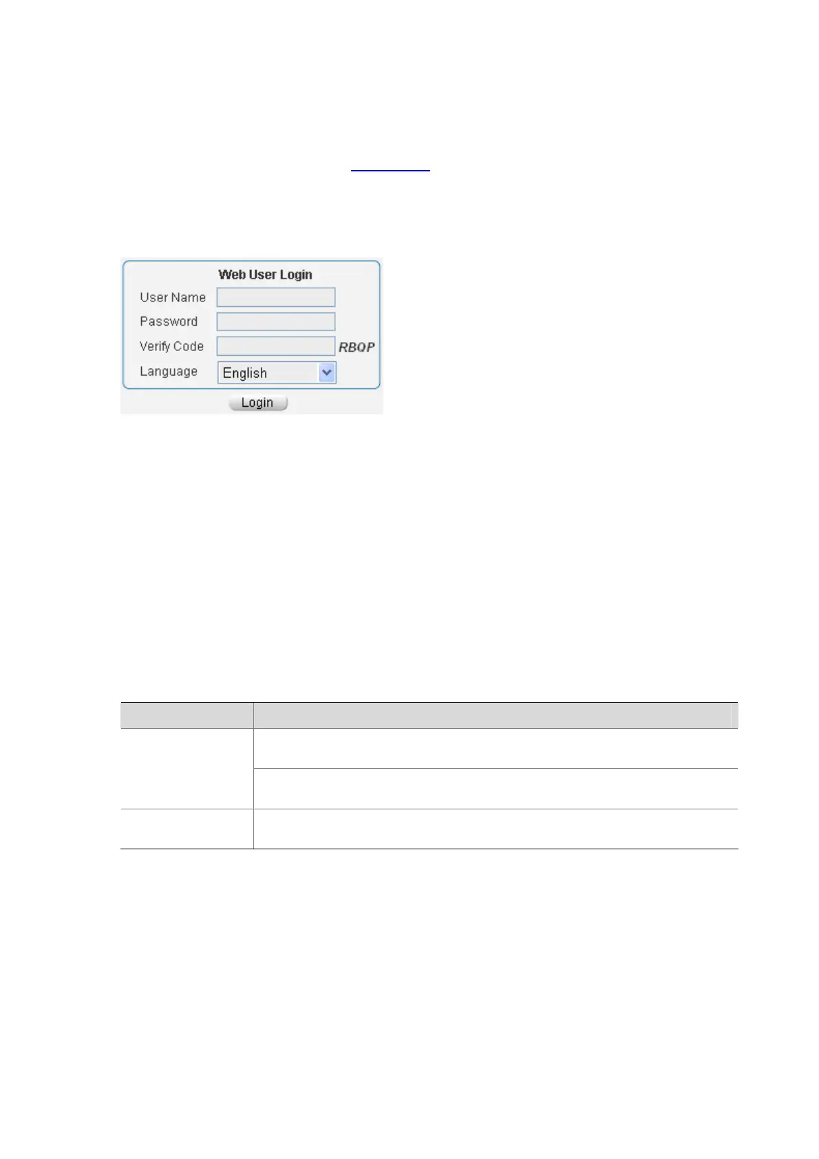
Step5 When the login interface (shown in
Figure 14-17) appears, enter the user name and the password
configured in step 2, select a language, and then click Login to log in to the main page of the
Web-based network management system.
Figure 14-17 The login page of the Web-based network management system
Logging In Through an NMS
Introduction
You can also log in to an AP through a network management station (NMS), and then configure and
manage the AP through the agent on the AP. The Simple Network Management Protocol (SNMP) is
applied between the NMS and the agent. For more information about SNMP, see SNMP in the Network
Management and Monitoring Configuration Guide.
To log in to an AP through an NMS, you need to perform related configuration on both the NMS and the
AP.
Table 14-9 Requirements for logging in to an AP through an NMS
Item Requirement
The IP address of the management VLAN of the AP is configured. The route between
the NMS and the AP is available.
AP
The basic SNMP functions are configured. (See SNMP in the Network Management
and Monitoring Configuration Guide.)
NMS
The NMS is properly configured. For more information about NMS, see the
corresponding manual shipped with the NMS.
 Loading...