18
Installation
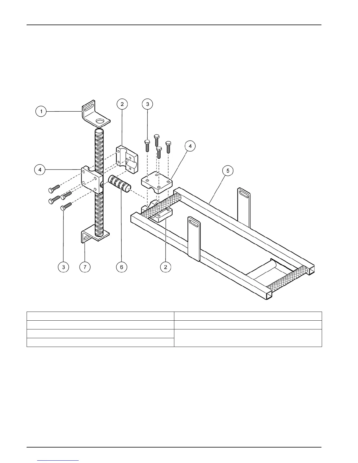
3. Position the other two clamp halves around the front end of the frame as shown in
Figure 8.
Note: In most cases the front of the frame will point toward the wall as shown in Figure 8 (see
also Figure 12 on page 23). If flow conditions require the sensor to point away from the wall,
use the 12-inch spacer and position the two clamp halves around the back end of the frame.
4. Connect the clamp halves together with four bolts. Lightly tighten the bolts to
temporarily hold the clamp in position.
Figure 8 Clamps assembled on wall bracket and frame
1 Adjustable wall bracket 5 Frame
2 Clamp half, threaded 6 Spacer
3 Clamp bolt, ¼–20 x 1 in. 7 Wall mount bracket
4 Clamp half, not threaded