Do you have a question about the Hach ORBISPHERE 410 and is the answer not in the manual?
Provides information about the accuracy and limitations of the manual.
Covers essential safety warnings, precautions, and hazard information for operating the instrument.
Explains the meaning of DANGER, WARNING, CAUTION, and NOTICE symbols used in the manual.
Details critical safety measures, including electrical hazards and proper installation practices.
States that only authorized personnel should service the analyzer.
Instructs users to read all labels and tags attached to the analyzer for safety.
Specifies the maximum operating altitude and potential risks at higher altitudes.
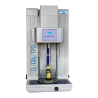
Describes the primary purpose and applications of the ORBISPHERE 410 Analyzer.
Provides information on the disposal and recycling of electrical equipment in Europe.
Explains Hach Lange's commitment to environmental responsibility regarding product disposal.
Contains information regarding hazardous substances for export to the People's Republic of China.
Lists detailed operational conditions, EMC requirements, CE compliance, and safety ratings.
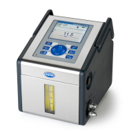
Describes the instrument's hardware components and their functions.
Explains how to identify the analyzer model and its configuration options.
Details access levels for different functions, defining user permissions.
Lists the factory default configurations for various instrument settings.
Guides users on how to unpack the instrument and check for any shipping damage.
Provides a step-by-step checklist to ensure a complete and correct installation of the analyzer.
Covers installation procedures for wall and pipe mounting the instrument.
Shows the physical dimensions of the wall and pipe mount instrument variants.
Details the procedure for attaching the instrument to a wall using provided brackets.
Details the procedure for mounting the instrument onto a pipe using clamps.
Illustrates and labels the connection ports on the bottom of the wall/pipe mount instrument.
Covers the installation process for instruments designed for panel mounting.
Shows the physical dimensions of the panel mount instrument.
Describes the steps for physically installing the instrument into a panel.
Illustrates and labels the connection ports on the bottom of the panel mount instrument.
Provides instructions on how to properly assemble and connect cables using the provided fittings.
Details the specific steps for wiring cables through waterproof glands, ensuring proper grounding.
Explains how to connect the instrument to the power source, covering both low and high voltage options.
Details the power connection for 10-30 VDC instruments using a 7-pin BINDER connector.
Details the power connection for 100-240 VAC instruments using a 4-pin male connector.
Guides on connecting various cables to the instrument's electronic boards.
Explains the type of sensor cable required and how to connect it to the measuring board.
Identifies and describes the main connectors on the instrument's electronic boards.
Details the specific connections available on the main board of the instrument.
Identifies the measurement boards for EC and TC sensors and their connector pinouts.
Explains the configuration and function of the measurement alarm relays.
Provides guidance on installing different types of sensors (EC and TC).
Refers to a separate manual for EC sensor installation, servicing, and maintenance.
Provides specific installation notes for TC sensors, including purge gas requirements.
Directs users to change the instrument's display language.
Explains how to set up user access rights and security levels for the instrument.
Describes the front panel interfaces including the touch screen, LED, and buzzer.
Details the touch screen display, its resolution, and the Windows CE-based interface.
Explains the purpose of icons in the header bar for login, display adjustment, and menu access.
Describes how to navigate through the instrument's menu system using tree views and controls.
Explains the use of rolling lists for selection and the on-screen virtual keyboard for input.
Explains the login process, authorization levels, and handling of warning messages.
Describes the types of warning messages displayed and the user confirmations required.
Provides a visual overview of the instrument's main menu hierarchy and navigation paths.
Describes different display modes like Numeric, Diagnostic, and Statistic views.
Details how to customize parameters for Numeric and Statistic view displays, including graph settings.
Covers basic instrument settings like measurement mode, units, and sensor membrane selection.
Details settings for EC and TC sensors, including gas units, alarms, filters, and thermal cutoff.
Explains how to configure settings for recording, storing, and managing measurement data.
Defines calibration types and general procedures for gas sensor calibration.
Provides detailed instructions for calibrating EC gas sensors in air or using direct value methods.
Specific steps for calibrating Oxygen (O2) sensors in air or using direct calibration.
Specific steps for calibrating Ozone (O3) sensors, noting stabilization time.
Provides detailed instructions for calibrating TC gas sensors.
Explains calibration errors, barometric pressure calibration, and calibration reports.
Explains common calibration errors and conditions that prevent successful calibration.
Guides users on calibrating the instrument's internal barometric pressure sensor.
Describes the information contained in calibration reports and their traceability features.
Allows setting a "snooze" time to temporarily stop instrument alarms.
Displays the current state of alarm relays and analog output values.
Covers the configuration and testing of the instrument's alarm and system relays.
Details how to configure and calibrate the instrument's analog output signals.
Explains the "Linear" and "Tri-linear" output characteristics and their configuration settings.
Guides on configuring the instrument for RS-485 communication, including data formats and examples.
Describes data formats for cyclic measurements and file transmission via RS-485.
Provides a practical example of using RS-485 communication with a PC via a converter.
Covers the installation and configuration of the PROFIBUS-DP communication module and its data.
Details the steps for installing the PROFIBUS-DP module and required jumpers.
Lists the data points available for the Profibus Input Buffer.
Explains the use of the USB-A port for data export/import and software updates.
Covers configuring the instrument for remote access via a web page using HTTP/TCP-IP.
Describes how to enable and configure the HTTP server for web-based access.
Details how to access the instrument's web interface from a PC using a browser.
Explains how to connect and use a printer to print reports from the instrument, including error messages.
Provides instructions for installing a ferrite core on the printer cable.
Lists common printer error messages and their meanings.
Guides on managing user access levels, IDs, and passwords for instrument security.
Details how to set up user access rights, session times, and action logging.
Explains how to add, edit, or delete registered users and their access levels.
Describes the function and content of the user action log file for traceability.
Allows users to select, modify, and configure product-specific settings for analysis.
Allows saving and recalling instrument configurations for different applications, including naming and selecting them.
Provides tools for diagnosing sensor issues, including calibration timers, service reminders, and current measurements.
Covers language selection, clock settings, screen adjustments, buzzer, boards info, and battery status.
Allows changing the instrument's display language, setting the clock, adjusting the screen, and configuring the buzzer.
Displays information about the instrument's hardware boards and the real-time clock battery status.
Covers software download for technicians and ending the application.
Emphasizes that instrument maintenance should only be performed by qualified service technicians.
Provides guidance on interpreting instrument events and messages for troubleshooting, including a list of events and alarms.
Lists various events and alarms, their descriptions, and associated bit masks for troubleshooting.
Provides guidelines for safely storing, handling, and transporting the instrument to prevent damage.
Lists available accessories for the Orbisphere 410/510 instruments.
Lists essential spare parts for the Orbisphere 410/510 instruments.
Defines common units used for gas measurements in the manual.
Provides definitions for general technical terms and concepts used throughout the manual.
| Technology | Optical |
|---|---|
| Power Supply | 100-240 VAC, 50/60 Hz |
| Parameter | Dissolved Oxygen |
| Accuracy | ±1% of reading |
| Response Time | t₉₀ < 30 s |
| Operating Temperature | -5°C to 50°C |
| Pressure Range | 0 - 10 bar absolute |
| Communication Interface | RS-232, USB, Ethernet |
| Sensor Type | Optical Dissolved Oxygen Sensor |