14
Installation
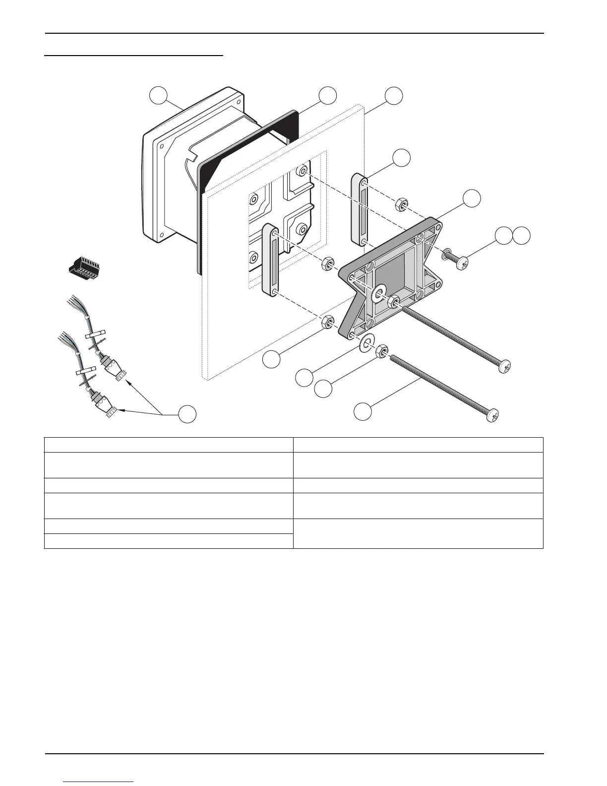
Figure 9 Panel Mounting the Controller
To remove the sensor connectors before inserting the controller enclosure into the panel
cut-out:
1. Disconnect the wires at terminal block J5, see Figure 19 on page 24.
2. Loosen and remove the nut securing the sensor connector inside the enclosure.
Remove the sensor connector and wires. Repeat step 1 and 2 for the other sensor
connector.
3. After the controller is in place in the panel, reinstall the sensor connectors and
reconnect the wiring to terminal J5 as shown in Figure 19 on page 24.
1. Controller 7. Lock washer, ¼-inch I.D., (4) Cat. No. 8H1336
2. Gasket, Neoprene, panel mount,
Cat. No. 1000A4F3249-101
8. Hex nut (4), Cat. No. 5867300
3. Panel (maximum thickness is 9.5 mm (
3
/8 inch)) 9. Flat washer (4), Cat. No. 8H1346
4. Mounting Foot (2), Cat. No. 1000B4F3222 10. Pan head screw, M6 x 1.0 x 150 mm (4),
Cat. No. 5867600
5. Mounting bracket, controller, Cat. No. 1000C4F3217-101 11. It may be necessary to remove the sensor connectors.
see procedure below.
6. Pan head screw (4), Cat. No. 5867400
1
2
3
4
5
6
7
8
11
9
8
10