18
Installation
The DC power source that supplies power to the 24 VDC powered sc100 must maintain
voltage regulation within the specified 24 VDC –15% +20% voltage limits. The DC power
source must also provide adequate protection against surges and line transients.
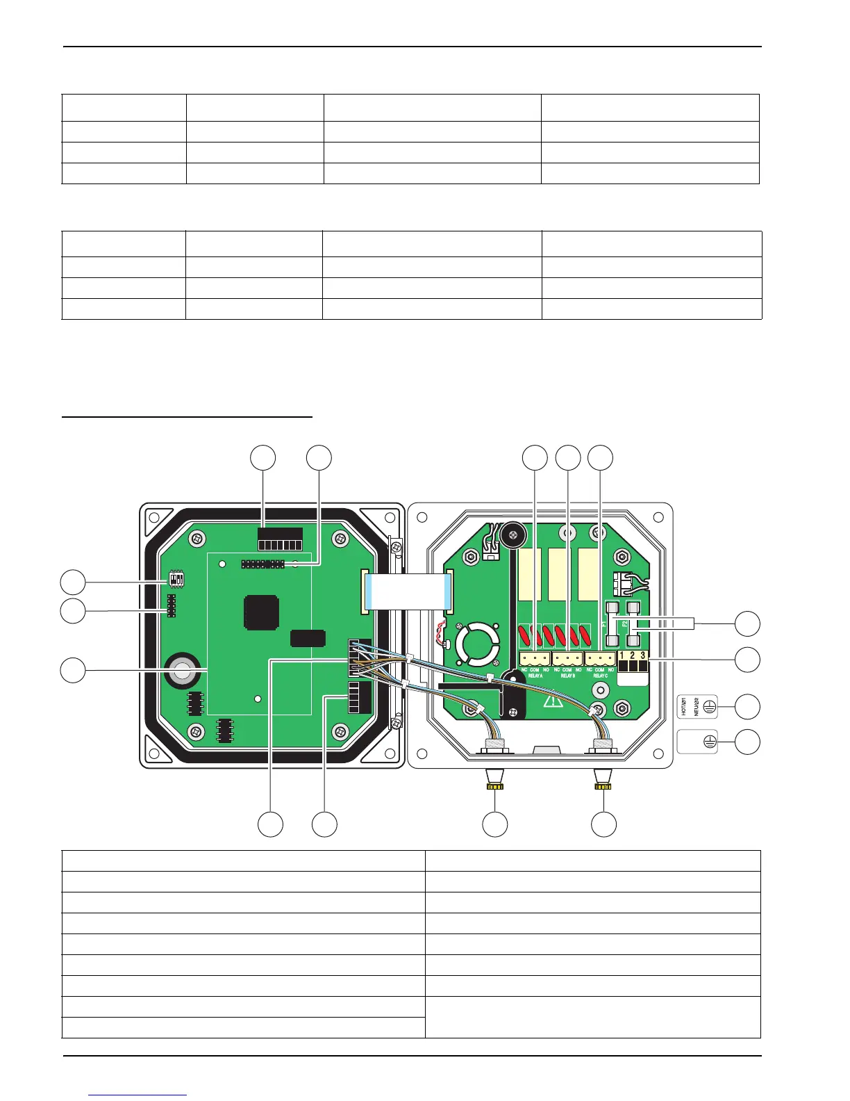
Figure 13 sc100 Wiring Connections
Table 2 AC Power Wiring Information (sc100 AC powered model only)
Terminal Number Terminal Description Wire Color Code for North America Wire Color Code for Europe
1 Hot (L1) Black Brown
2 Neutral (N) White Blue
3 Protective Earth (PE) Green Green w/yellow tracer
Table 3 DC Power Wiring Information (sc100 24 VDC powered model only)
Terminal Number Terminal Description Wire Color Code for North America Wire Color Code for Europe
1 +24 V dc Red Red
2 24 V dc return Black Black
3 Protective Earth (PE) Green Green w/yellow tracer
1. J1—Network connector 8. Sensor connector
2. J2—Header for optional network interface card 9. Sensor connector
3. J5—Relay A connector 10. J6—Analog output (4–20 mA) connector
4. J6—Relay B connector 11. J5—Sensor connector for hard-wiring
5. J7—Relay C connector 12. Position for network interface card
6. Fuses (F1, F2) 13. Service port
7. J8—Power connections 14. Sensor terminator selector/service port configuration
a. AC Power connection (AC powered sc100 model only)
b. DC Power connection (24 VDC sc100 model only)
NCNCNC
COMCOMCOM
NO
F1
F2
NONO
RELAY CRELAY BRELAY A
J1
J2
J4
NETWORK
INTERFACE
CARD
J3
J5
J6
U5
U9
S1
6
7
7a
7b
14
12
13
312
89
45
11 10
+24 VDC
 Loading...