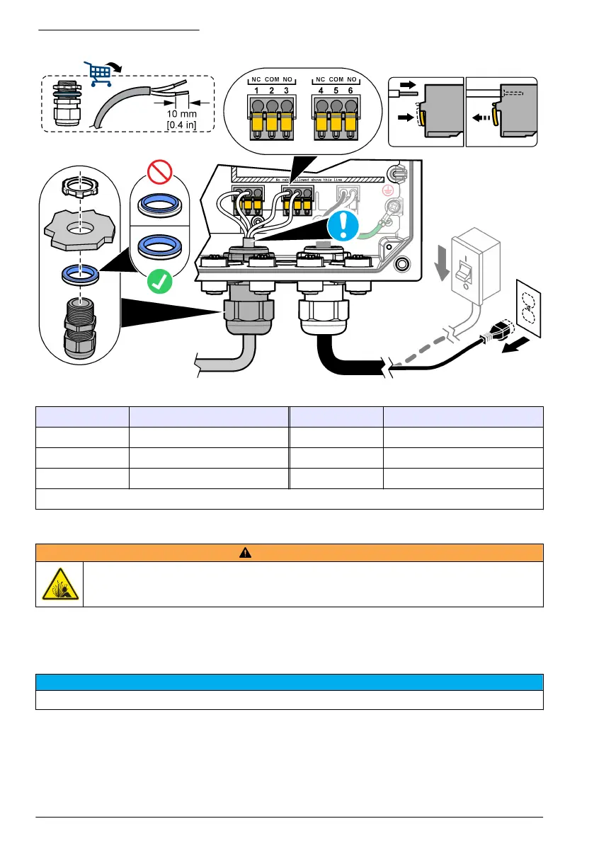
Figure 10 Connect the relays
Table 4 Wiring information—relays
Terminal Description Terminal Description
1 Relay 1, NC 4 Relay 2, NC
2 Relay 1, common 5 Relay 2, common
3 Relay 1, NO 6 Relay 2, NO
NC = normally closed; NO = normally open
Install an expansion module
W A R N I N G
Explosion hazard. This manual is only for installation of the unit in a non-hazardous location. For
installation of the unit in hazardous locations, use only the instructions and approved control drawing
provided in the hazardous location installation manual.
Expansion modules with analog outputs, analog inputs and Profibus communication are available for
the controller. Refer to the documentation supplied with the module for additional information.
Close the cover
N O T I C E
Close the controller cover and make sure that the cover screws are tight to keep the environmental rating of the
After the power connections are made, install the high-voltage barrier. Make sure that the high-
voltage barrier is correctly put on the enclosure guides and fixed to the main PCBA. Refer to Figure 8
on page 14.
Close the controller cover. Tighten the cover screws with a maximum torque of 1.4 Nm (12.4 in./lb).
Refer to Figure 7 on page 13.
18
English

 Loading...