Connect a digital sc sensor
W A R N I N G
Explosion hazard. This manual is only for installation of the unit in a non-hazardous location. For
installation of the unit in hazardous locations, use only the instructions and approved control drawing
provided in the hazardous location installation manual.
A digital sc sensor can be connected to the controller using the keyed quick-connect fitting. Refer to
Figure 6 on page 12 and Figure 11. A digital sensor can be connected with the controller powered on
or off.
The controller automatically finds connected sensors. The sensor status LED on the front panel
flashes blue during the connection procedure. When the light stays on, the connection of the sensor
is correct. Refer to User interface on page 19. Use the mobile application to configure and operate
the connected sensors.
Retain the connector cap to seal the connector opening in case the sensor must be removed.
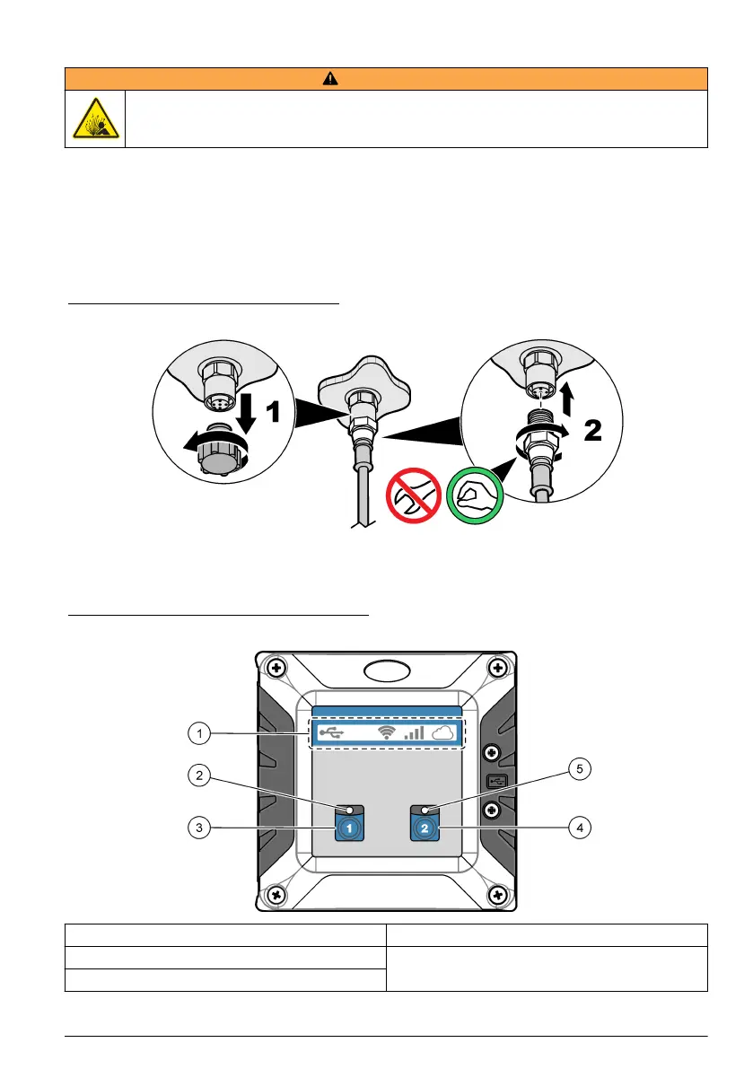
Figure 11 Digital sensor quick connect
User interface
The keypad has controller icons, sensor status LEDs and two channel buttons. Refer to Figure 12.
Figure 12 Keypad and front panel overview
1 Controller icons 4 Channel 2 button—Puts all channel outputs on hold.
2 Sensor status LED for Channel 1 5 Sensor status LED for Channel 2
3 Channel 1 button—Puts all channel outputs on hold.
The front panel has icons at the top that shows the controller condition. Refer to Table 5.
English
19

 Loading...