Seite 10 von 62
Brushless DC Controller HST-350
Orginalbetriebsanleitung Rev1.3
Montage und Inbetriebnahme
4. Montage und Inbetriebnahme
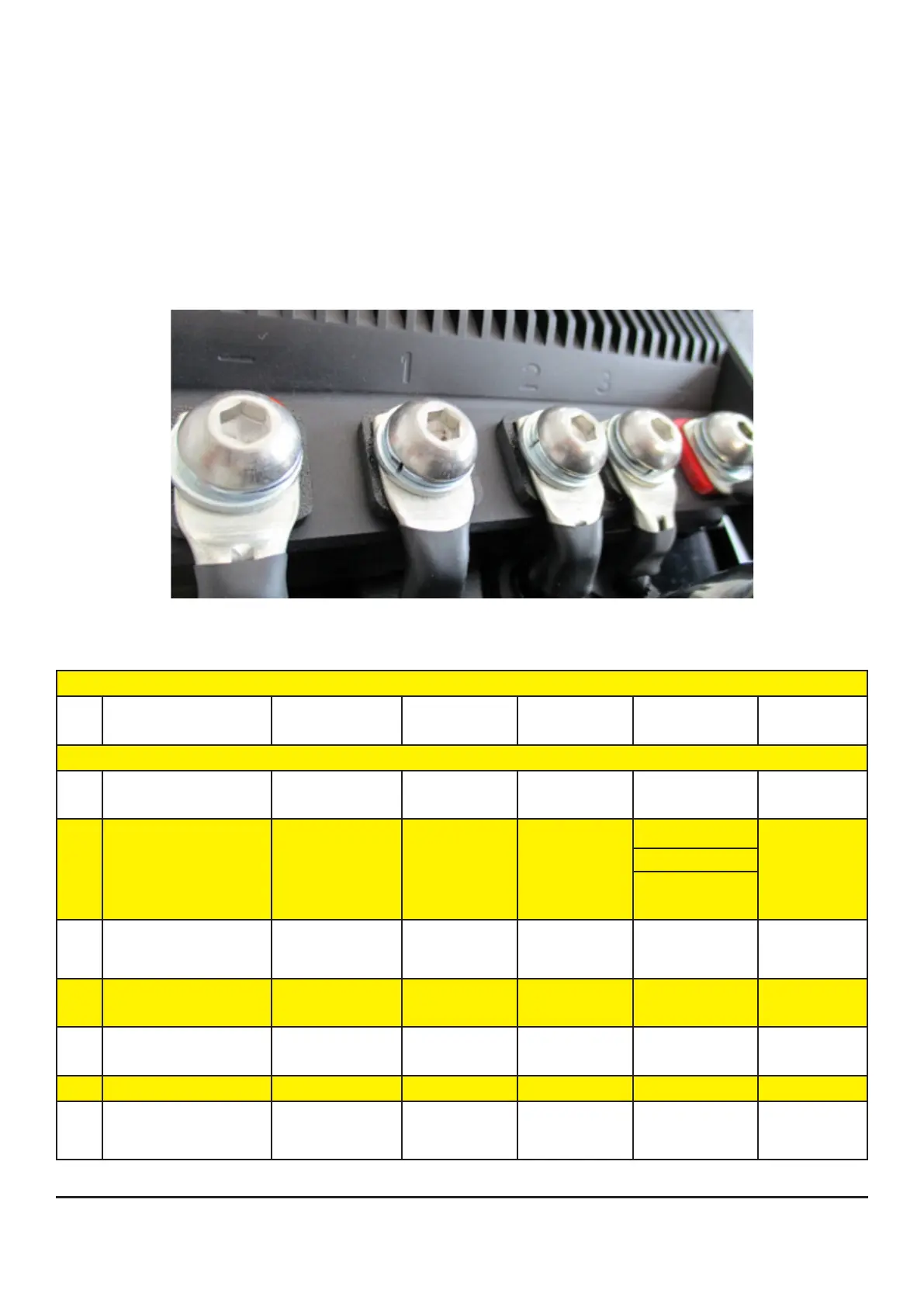
4.1 Anschluss Phasen- und Akkukabel
Für die Verkabelung zwischen Regler und Motor, sowie Regler und Akku ist selbst zu sorgen.
Achten Sie auf die passenden Querschnitte zur Leistung.
Es ist vorgesehen die Phasen- und Akkukabel mit M10-Linsenkopfschrauben (Anzugsdrehmoment
17Nm) zu befestigen.
Bringen Sie dazu passende Ring- oder Rohrkabelschuhe an den Kabeln an.
4.2 Belegung Sensorschnittstelle
35 pole socket ESC of HST-350
Pin Signal description Signal
SW/HW
VDC Function Description Pin / Colour
1 signal ground of T-
sensor (pin3)
GND 0 GND
T-Sensor
10 pole 10 / black
2 Ignition Key / Klemme
15
ON/OFF battery:
32.0 – 58.8
input (digital) V_Bat
switch
(or optional:
Display)
3 motor temperature of
coil U
T_Mot-U 15 input (analog) 10 pole 5 / white
4 motor temperature of
coil V
T_Mot-V 15 input (analog)
5 motor temperature of
coil W
T_Mot-W 15 input (analog)
6 Signal Ground GND 0 GND
7 accumulator tempe-
rature
T_Bat-1 5 input (analog) For use with
KTY83 sensor