Seite 13 von 62
Brushless DC Controller HST-350
Orginalbetriebsanleitung Rev1.3
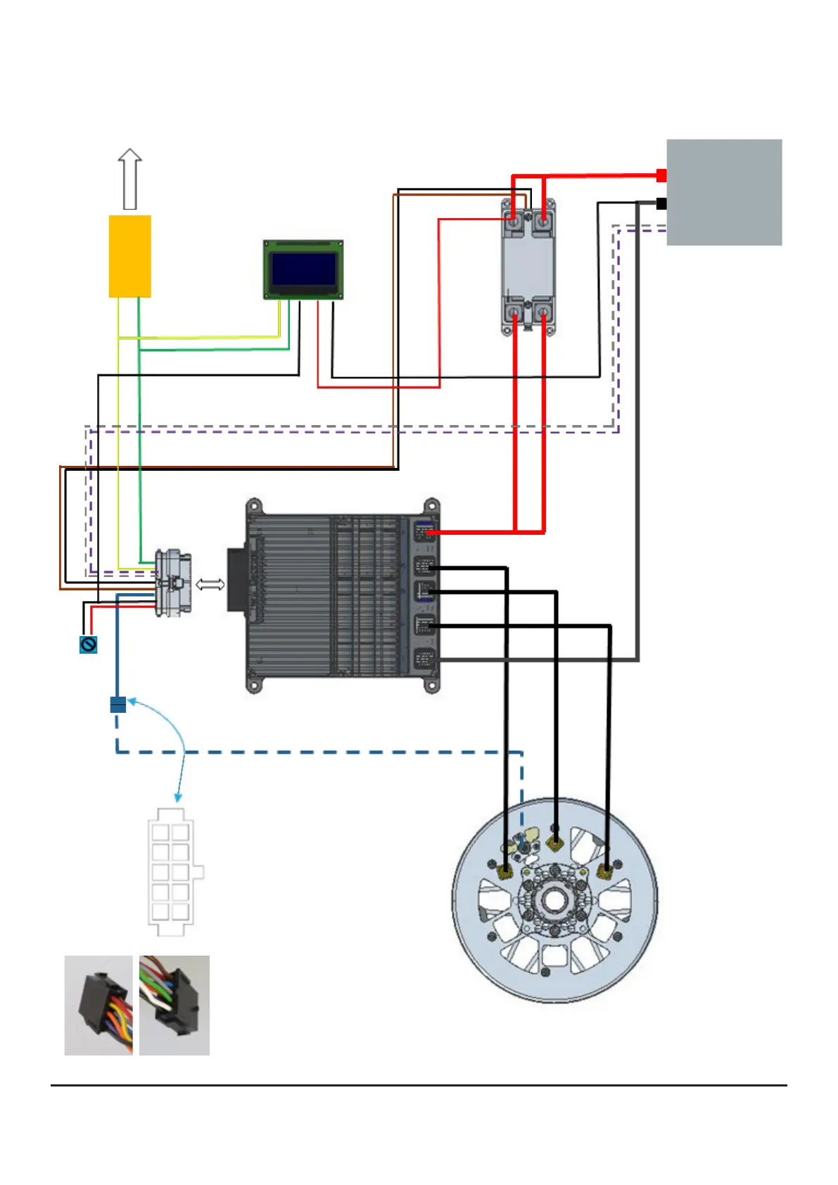
4.3 Anschlussschema
Montage und Inbetriebnahme
PC
CAN-
Adapter
2
1
3
4
5
6
7
8
9
10
Würth WR-MPC3,
10-polig, 2-reihig,
Sicht auf Kabelseite von
HST-350 aus
Kabel von 35-poligem Stecker
1) Pin 1; schwarz – GND-Temp
2) Pin 28; lila – n/a
3) Pin 30; orange – n/a
4) Pin 24; gelb – Hall Sensor 1
5) Pin 35; rot - Power supply 5V
of Hall sensors
6) Pin 3; weiß - Motor Temp. U
7) Pin 29; grün – n/a
8) Pin 26; grau – Hall Sensor 3
9) Pin 25; blau – Hall Sensor 2
10) Pin 14; braun – GND - Hall
Sensorkabel (optional)
Controller
HST-350
35-poliger
Stecker
+L3L2
L1
-
HerSi-Relais
mit Gehäuse
#10108207
Akku
32,0 -
58,8 VDC
L1
L2
L3
Motor