Equipment and Disposable Description P/N 53063-50, Manual Revision: B
2-4
CONTROLS AND INDICATORS
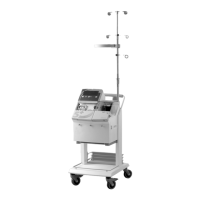
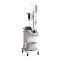
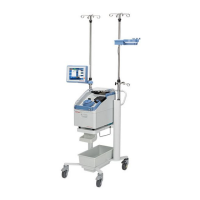
Figure 2-1 shows the CS5+. The control panel consists of a plastic covered key
pad section, a backlit key pad section, and the display screen. Only the necessary
readouts are illuminated, thus helping the operator to focus on information
needed. All control panel components are covered to protect the system from
spills and to allow easy cleaning. The control panel is shown in Figure 2-2.
Figure 2-2: Control panel
ON/OFF Power
Switch and
Fusing
The ON/OFF power switch is located on the right side of the system. This
machine is a two-fuse system. The primary fuse is located in the power entry
module in the back of the machine. The secondary fuse is internal on the power
supply and should only be replaced by trained service personnel.
Display Panel The display panel of the CS5+ provides important information regarding the
functioning of the system. As statistics change, they are updated on the display.
For example, should the pump reduce speed from 1000 ml/min to 750 ml/min
the readout on the display will change from 1000 to 750.
During normal operation the display is segmented so that the same type data will
be displayed in the same area for all protocols. The display is segmented into
three main areas: 1. The left section provides general information regarding the
state of the system. 2. The right section provides procedure data, mode of
operation, and information regarding the programmable parameters. 3. The
bottom area of the display is used to provide user prompts. Figure 2-3 shows a
typical display.
Auto
Manual
Start Stop
Mode
Help