- 7 -
5 ADJUSTING YOUR MACHINE
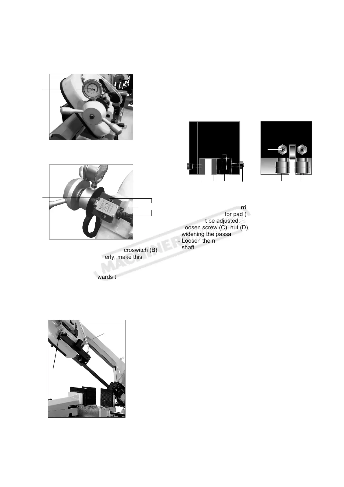
5.1 Blade tension assembly
The ideal tension of the blade is achieved rotating the
handwheel until the needle reaches the proper blade
tension on the tension gauge (A).
The machine will not operate if the microswitch does
not actuate by contacting the touch plate (C).
If the tension is set properly, but the microswitch (B)
does not contact or trigger properly, make this
adjustment.
- Loosen the setscrews (D).
- Push the microswitch (B) towards the touch plate (C).
Make sure that the plunger is pressed properly.
- Tighten down the setscrews (D) to secure the
microswitch (B) in place.
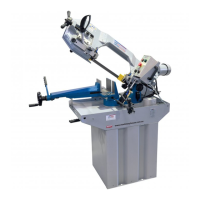
5.2 Adjusting the blade guide
- Disconnect the machine from the power source.
- Use a Hex. Wrench to loosen Hex. Socket screw (A)
on the square lock plate.
- Hold the handle (B) and slide blade guide block as
close as possible to the material without interfering
with the cut
- Tighten the hex. socket screw (A).
- Reconnect the machine to power source.
Blade guide blocks
The blade is guided by means of pads and bearings
that are set in place during inspection as per the
thickness of the blade with minimum play as shown in
the figure. In case the blade needs to be replaced,
make sure to always install 0.9mm thick blades for
which the blade guide pad and bearings have been
adjusted.
For saw blades with a different thickness, the
adjustment should be carried out as follows:
Note: the position for pad (A) and bearing (F) are fixed
and cannot be adjusted.
- Loosen screw (C), nut (D), and setscrew (D) to
widening the passage between the pads (A and B).
- Loosen the nut (G) and setscrew (G) and rotate the
shaft screw (E) with a flat head screwdriver to widen
the passage between the bearings (E and F).
- To mount the new blade: adjust the pad (B) to the
blade then loosen the setscrew to allow a play of 0.04
mm for the movement of the saw blade. Lock the
nut (D), screw (D), and screw (C), Rotate the shaft (E)
until the bearings rest against the blade as indicated
in the figure and then secure the setscrew (G) and
nut (G).
5.3 Saw frame return stroke-limiting device
It consists in a mechanical adjustment system,
mounted parallel to the saw frame rise cylinder, to
reduce the passive phases of the operating cycle. In
other words it eliminates the idle stroke that takes
place when the size of the part to be cut is much
smaller than the maximum cutting capacity. Practically,
you adjust the starting position of the blade in proximity
of the part, independently of its dimensions.
Operate as follows:
- Slightly open the flow regulation valve (H).
- Bring the blade as near as 10mm from the work piece
with the bow up/bow down switches (C and D).
- Loosen handle (7) to release the adjustable stop (8)
against the limit switch (9).
- Lock the handle (7)
ATTENTION:
- It is not necessary to adjust the mechanical stop (8)
every time; bring the blade near the workpiece by
B
A
A B C D E
G
F
A
B
C
D
Instruction Manual for EB-270DSA (B066)