- 8 -
means of bow switch (D) and then start the automatic
cutting cycle (F), which will begin operation from this
position of the blade.
- The bow will return to the upper end stroke.
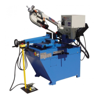
5.4 Changing the blade
To change the blade:
- Lift the saw arm.
- Loosen the blade with the hand wheel, remove the
mobile blade-guard cover, open the flywheel guards
and remove the old blade from the flywheels and the
blade guide blocks.
- Assemble the new blade by placing it first between
the pads and then on the race of the flywheels,
paying particular attention to the cutting direction of
the teeth.
- Tension the blade and make sure it perfectly fits
inside the seat of the flywheels.
- Assemble the mobile blade-guide end, the flywheel
guard, and fasten it with the relative knobs. Check
that the safety microswitch is activated otherwise
when electric connection will be restored the machine
will not start.
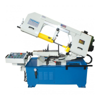
5.5 Adjusting the blade to the flywheels
1. Loosen the hex nut screws A, B, and C.
2. Use an Allen wrench on set screw D to adjust the
tilt of the flywheel.
-Turning the set screw D clockwise will tilt flywheel so
that the blade will ride closer to the flange.
-Turning the set screw D counter-clockwise with tilt the
flywheels that the blade will ride away from the flange.
If the blade rides away too far then it will come off.
After the adjustment is finished, fasten the hex nut
screws in this order: A, B, and C.
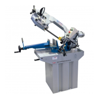
Checking the adjustment of the blade
Use a strip of scrap paper and slide it between the
blade and the flywheel while it is running.
-if the paper is cut then the blade is riding too close to
the flange. Re-adjust.
-if you notice that the blade is riding away from the
flange. Then re-adjust.
WARNING: Always assemble blades having
dimensions specified in this manual and for which the
blade guide heads have been set; otherwise, see
chapter on "Description of the operating cycle" in the
section Starting-up.
5.6 Replacing saw frame return spring
- When performing this operation it is necessary to
support saw arm using the lifting device.
- Replace the spring by loosening the upper coupling
rod and releasing it from the lower tie-rod.
6 ROUTINE AND SPECIAL
MAINTENANCE
THE MAINTENANCE JOBS ARE LISTED BELOW,
DIVIDED INTO DAILY, WEEKLY,
MONTHLY AND
SIX-MONTHLY
INTERVALS. IF THE FOLLOWING
OPERATIONS ARE NEGLECTED, THE RESULT
WILL BE PREMATURE WEAR OF THE MACHINE
AND POOR PERFORMANCE.
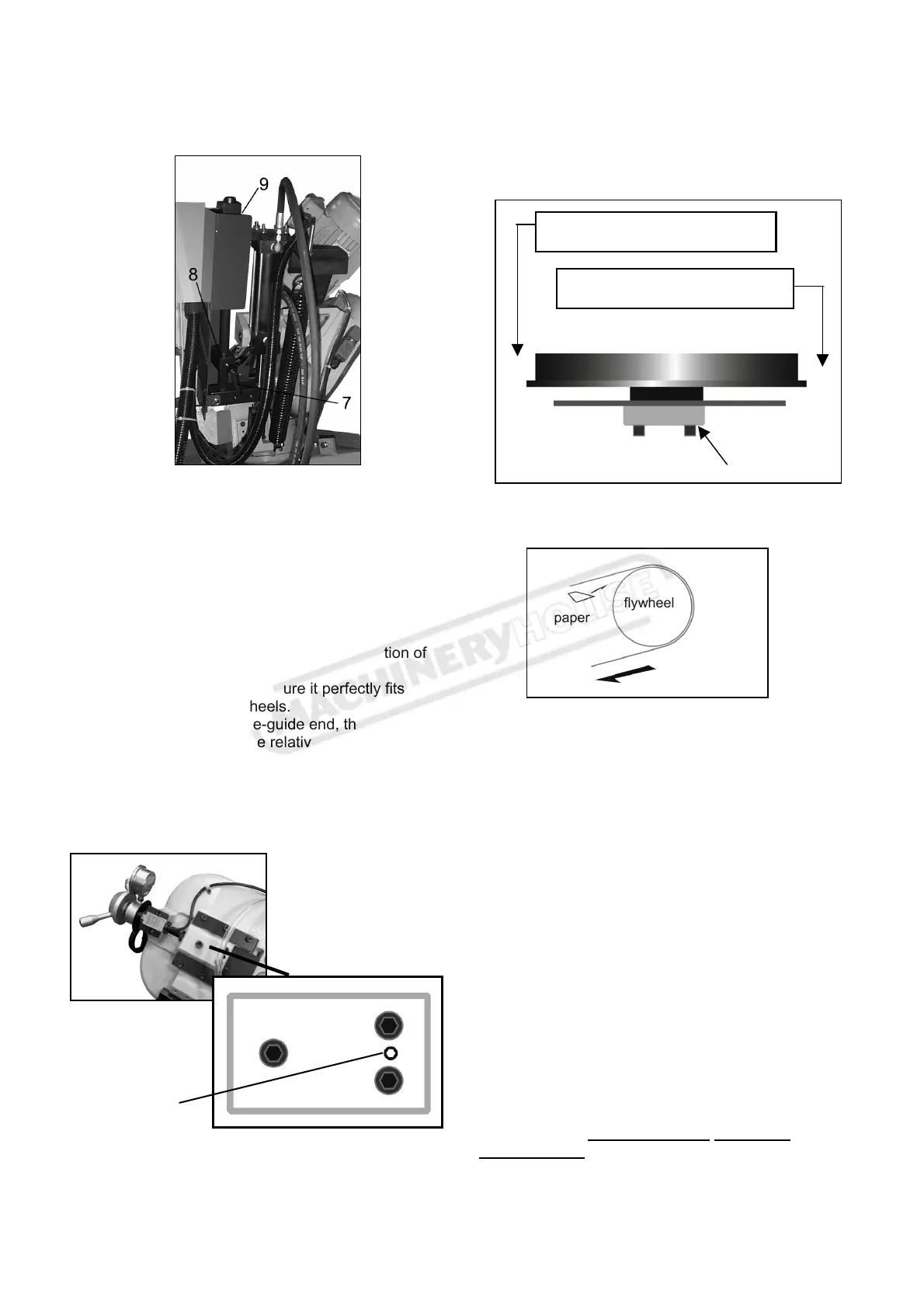
A Tilt in this direction will cause the
l
ri
w
r
h
fl
n
A Tilt in this direction will cause the
l
ri
w
fr
m
h
fl
n
Top view
Set screw D
paper
Blade direction
flywheel
TOP
A
C
B
Set screw D
Instruction Manual for EB-270DSA (B066)