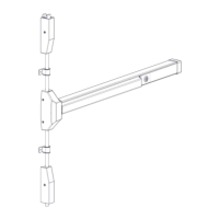
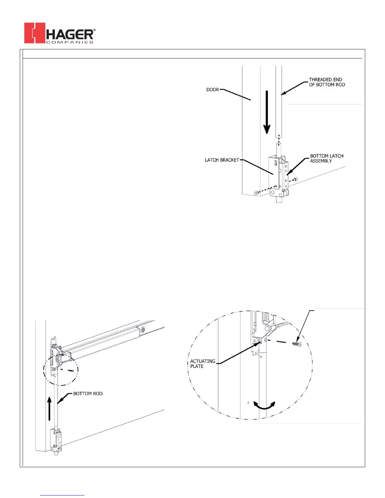
STEP 1: Install bottom latch assembly to bottom latch
bracket using provided screws and bottom two
holes in bracket (see figure 1)
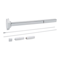
STEP 2: Screw threaded end of bottom rod halfway onto
bottom latch assembly.
STEP 3: Before aligning the top end of the bottom rod with
the actuating plate, lift up on the bottom rod until
you feel the resistance from the bottom latch
spring. At this point, stop pulling up (see figure 2).
STEP 4: Continue holding rod up while aligning the top end
of the bottom rod with the actuating plate. Align
by rotating rod clockwise or counterclockwise until
the holes line up (see detail A).
STEP 5: Use the provided machine screw to attach rod to
actuating plate. Be sure actuating plate on the
chassis is in the down position (see detail A).
NOTE: The bottom latch assembly has a security feature.
This requires the bottom rod to be adjusted as
described above. Be sure there is no slack in the
bottom latch. To check for slack, grab the bottom
rod and pull up. If it doesn’t pull the latch bolt up
immediately, there is too much slack. Disconnect
the top of the bottom rod, screw bottom rod
further onto bottom latch assembly. Reconnect top
end and check again.
CHECK INSTALLATION by pushing on exit device push bar.
Make sure bottom latch is retracted when push bar is
depressed. Bottom latch should clear the finished floor, strike,
or threshold. Bottom latch should have 3/8” throw.
 Loading...