powerway enclosures and components
U-PWE/U-PWK
U-PW powerway System Manual 39
Form of internal separation
Solid door
3 module doors
Can be operated from the outside
Can be operated behind the door
Type of functional unit design
Plug-in technology/fixed installation -F
Plug-in insertion technology -W
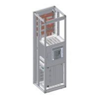
Device compartment: Functional units with air circuit breaker
1600 A (rear connection and front connection)
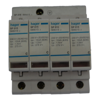
Switch/circuit breaker designation
Rated current switch/circuit breaker I
nc
Field connection positions from ACB to the main busbars
Rated operational voltage U
e
Rated short-time withstand current I
cp
Rated peak withstand current I
pk
Type of functional unit design
Position 1, main circuit/device input
Position 2, main circuit/device outlet
Position 3, auxiliary circuit
F = fixed connection (with tools)
D = drawable connection (without tools) W = guided connection
Number of installable circuit breakers
Device installation position
Neutral conductor disconnector up to 2000 A (NP1250,
NP2250), detachable separation
Position of N/PEN separation
Terminal compartment or device compartment
Terminal compartment
Cable connection, current bar connection up to 1600 A
Cable connection cross sections
Position of the PE conductor
Horizontal, Cu rail lying
 Loading...