18
Installation and Maintenance Manual, Compact CA
Instruction to follow when mounting
the COMPACT CA motor on a driven
shaft
Before the motor is mounted there are some
preconditions which must be fulfilled:
- The shaft material for the driven shaft must
be of a quality which meets the minimum re-
quirements specified by Hägglunds. (See our
recommendations, table 3.2.
- The shaft must have the dimensions as
recommended in the section 3.1.
- You should note that the couplings are from
the factory lubricated with MoS
2
(Molykote) on
the conical surfaces and the bolts. This lubri-
cants shall remain on those surfaces but:
It is therefore important that you clean your
hands free from Molykote.
If those conditions are fulfilled you may start
the mounting.
- Clean the driven shaft and the out- and inside
of the Compact CA motor hollow shaft. Use
acetone or similar.
- Remove the spacers between the two clamp-
ing rings of the coupling.
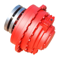
- Mount the coupling on the hollow shaft of
the motor. The coupling must be pushed right
up to the stop of the shaft.
- Mount the motor onto the driven shaft by
following the instruction in the section 3.1.4
"Mounting the motor onto the driven shaft".
(With or without using the mounting tool).
3.1.2 Mounting the coupling onto the motor shaft
Molykote must under no
circumstances be trans-
ferred to the surfaces be-
tween the driven shaft and
the motor.
However for the tightening of the coupling
screws the following must be observed:
Keep tension in your lifting wires to avoid a
skew setting of the motor on the shaft dur-
ing the tightening of the screws. Wobbling
caused by a skew setting of the motor gives
extra forces on the main bearings.
In order to avoid the misalignment of the two
clamping rings during the screw tightening, the
gap between the rings must be measured in
several places during the process, see figure
3.14. The difference between the measured
gaps must never vary more than 1 mm (0.04")
during any stage of the tightening process.
Pre-set the coupling screws in opposite pairs
(12-6-3-9 o'clock) until you reach maximum
50% of the torque specified for the screws. It is
very important that when you reach this stage
the misalignment is controlled as described
above.
Mark the screw head (at 12 o'clock) with a
pen or paint so that you can follow the turning
sequence of the screws.
Set the torque wrench for the specified maxi-
mum torque. Tightening torque of the coupling
screws; see the sign on the coupling, or table
3.9.
Now start tightening the screws in sequence
shown in figure 3.14a.
Keep on doing this until you have reached the
stated torque. Several passes are required
before the screws are tightened to specified
torque. Keep checking the alignment of the
coupling. (15-20 passes may be necessary).
When the specified torque is reached it is
important that all screws are tightened with
specified torque and that no further movement
can be observed.
Installation
Never tighten the coupling
screws until the motor has
been mounted onto the
driven shaft.