31
Installation and Maintenance Manual, Compact CA
Installation
* Pressure in brake cylinder = 0 bar.
** See diagram 3.1. High pressure reduce service life for seals and axial bearing.
21
(0,83)
BSP 3/4"
(2,1)
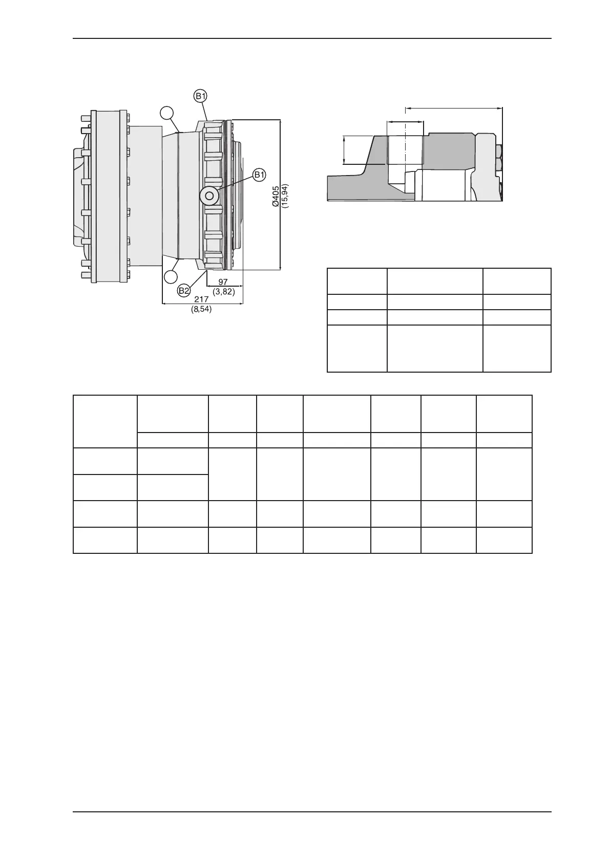
Figure 3.25
Figure 3.26
3.1.10 Brake MDA 5, 7 & 10
B1 and B2
Brake
Torque*
dynamic
Begins
to open
at**
Fully
open
at**
Opening
pressure
(min-max)
Displace-
ment.
max
Weight Oil volume
Nm (lbf·ft) bar (psi) bar (psi) bar (psi) cm
3
(in
3
) kg (lbs) l (US gal)
MDA 5-16
13600 ± 400
(10000 ± 295)
16
(232)
19
(276)
20-25
(290-363)
155
(9.5)
100
(220)
1.7
(0.45)
MDA 5-26
22600 ± 700
(16700 ± 520)
MDA 7-34
30400 ± 900
(22400 ± 660)
16
(232)
19
(276)
20-25
(290-363)
195
(11.9)
100
(220)
1.7
(0.45)
MDA 10-48
41500 ± 2000
(30600 ± 1480)
16
(232)
19
(276)
20-25
(290-363)
256
(15.6)
100
(220)
1.7
(0.45)
Connection Description Port connec-
tion
B1 Brake connection G 3/4"
B2 Alt. brake connection G 3/4"
F3, F4 Flushing connection
(For flushin of motor
axial bearing)
G 1/4"
Table 3.10
Table 3.11