49-7835 Rev. 8 11
ENGLISH
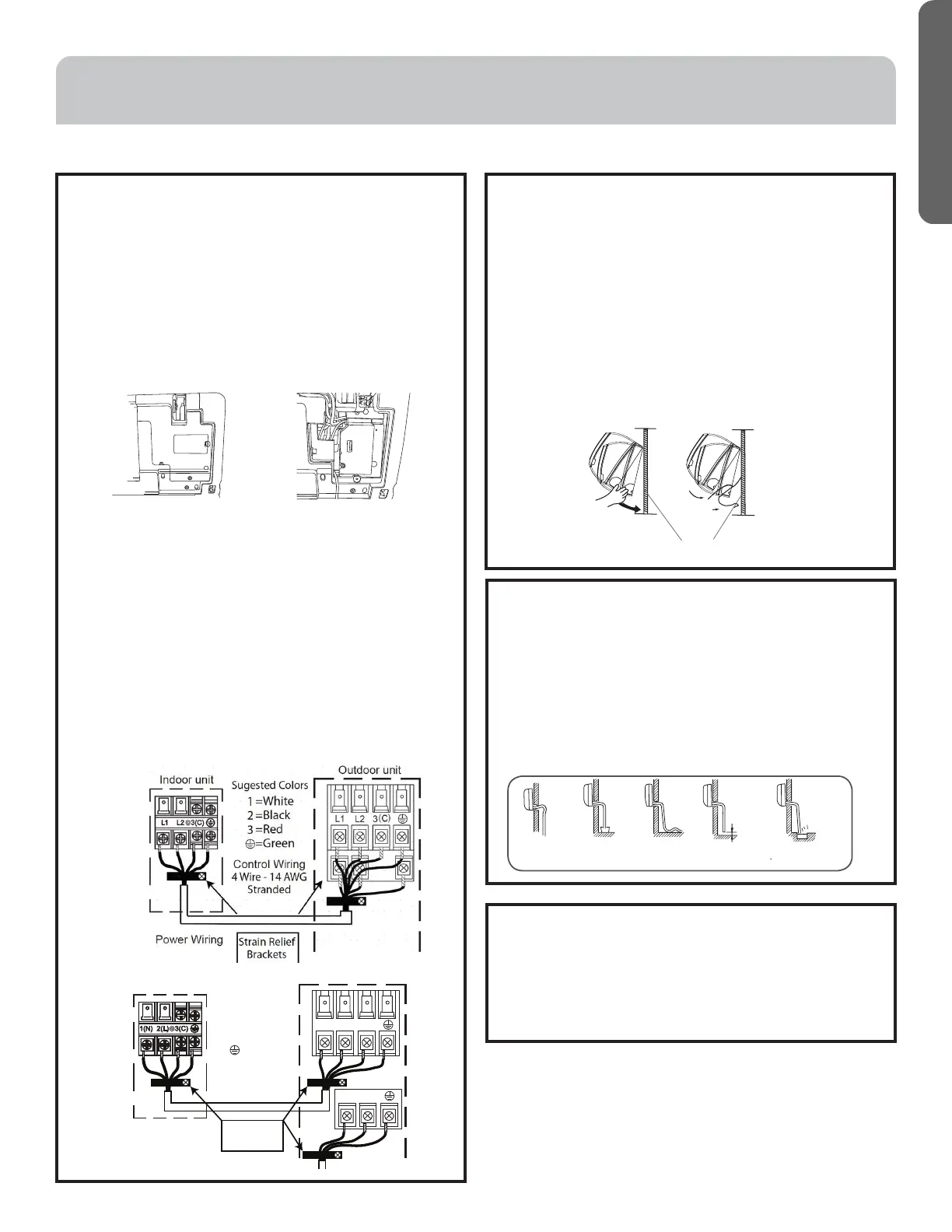
D. Electrical Connections for the Indoor Unit
NOTE: Be certain all wiring complies with local building
codes and NEC and that the supply voltage for this
system is correct.
• Place the indoor unit on a solid work surface before
making electrical connections.
• Both the outer plastic and inner galvanized steel
cover plates must be removed to make the electrical
connections for the indoor unit.
• Raise the front cover to access the screws for
removing these covers.
• Route the 14/4 AWG wiring through the slot in the
back of the unit and into the front access panel.
• Using a wire stripper, remove the insulation and
separate the 4 wires.
• Make wiring connections at each terminal according
to wiring diagram. Take note of the color of the wire
at each terminal and ensure the wires are connected
to the outdoor unit accordingly.
• Ensure each wire is under the screw terminal plate
and the plate is tightened.
• Ensure the 14/4 cable is secured under the strain
relief bracket.
• After the terminal block wiring is completed, replace
both cover plates and lower the front casing.
mounting plate
Step 2 - Installation of the Indoor Unit (Cont.)
E. Mount Indoor Unit to Mounting Plate
• Bundle the refrigerant piping, drain piping, and
wiring with tape and carefully rout the bundle
through the piping hole.
• With the top of the indoor unit closer to the wall,
hang the indoor unit on the upper hooks of the
mounting plate. Slide the unit slightly side to side
to verify proper placement.
• Rotate the lower portion of the indoor unit to the
mounting plate, and lower the unit onto the lower
hooks of the mounting plate. (see illustration)
• Verify the unit is secured and flush to the wall.
• Indoor Unit installation is finished at this time.
G. To Remove the Indoor Unit
• Slightly raise the entire unit.
• Pull the lower portion of the unit off the lower
hooks and pull slightly away from the wall.
• Lift the upper portion of the unit off the upper
hooks.
It becomes
high midway.
The gap with the
ground is too small
There is the bad
smell from a sewer
It waves.
The end is imm-
ersed in water.
Less than
5cm
F. Condensate Drainage Pipe
• Verify the condensate drain line has a constant
pitch downward for proper water flow. There
should be no kinks or rises in the tubing which
may cause a trapping effect of the water (see
illustration).
Optional: Can use PVC pipe by connecting a 1” ID
PVC pipe to the drain line coming out of the wall
and running to desired location.
INSTALLATION INSTRUCTIONS
*NextGen Arctic Series
Outdoor unit
3
2
1
)
(
C
L2
L1
Indoor unit
Control Wiring
4 Wire - 14 AWG
Stranded
1
2
3
=White
=Black
=Red
=Green
Sugested Colors
Strain Relief
Brackets
*Tempo 230V series
 Loading...