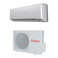
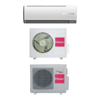
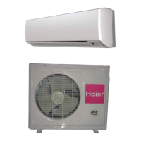
Outdoor
Unit
Loading of the battery
1
2
3
4
Parts and Functions
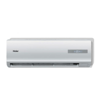
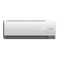
Indoor Unit
Actual inlet grille may vary from the one shown in the
manual according to the product purchased
OUTLET
INLET
CONNECTING PIPING AND ELECTRICAL WIRING
DRAIN HOSE
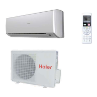
Remote controller
Remove the battery cover;
Load the batteries as illustrated.
2 R-03 batteries, resetting key
(cylinder);
Be sure that the loading
is in line with th
e" + "/"-";
Load the battery,then put on the cover again.
Inlet grille
Inlet
Air Purifying Filter
Outlet
Horizontal flap
Display board
(adjust up and do wn air flow
Don't adjust it manually)
(adjust left and right air flow)
Vertical blade
Emergency
Switch
Anion generator
(inside)
The distance between the signal transmission head and the rece-
iver hole should be within 7m without any obstacle as well.
When electronic-started type fluorescent lamp or change-over
wireless telephone is installed in the
ver is apt to be disturbed in receiving
the signals,
so the distance to the indoor unit should be shorter.
type fluorescent lamp or
room, the recei
Note:
Full display or unclear display during operation indicates the
ries have been used up.
Please change batteries.
If the remote controller can't run normally during operation, please
reload several minutes later.
batte
remove the batteries and
Remove the batteries in case unit won't be in usage for a long period.
If there are any display
after taking-out, just need to press reset key.
Hint:
Operation mode
AUTO
FAN
COOL DRY
Remote controller
HEAT
LOW HI
MED AUTO
If pressed, the other buttons
will be disabled. Press it once
again,lock will be cancelled.
30
.
LOCK
button
When the remote
RESET
button
controller appears
abnormal, use a sharp
pointed article to press
this button to reset the
1
.
Control the lightening and
the indoor
extinguishing of
LED display board.
remote controller normal.
2.LIGHT button
3. TIMER button
4. CLOCK button
8. HEALTH button
6. MODE button
7. HOUR button
9. ON/OFF button
10. TIMER ON display
11. FAN SPEED display
12. LOCK display
13. SWING UP/DOWN display
14. SLEEP display
15. HEALTH display
16. Operation mode display
17
.Singal sending display
18. POWER/SOFT display
19. Left/right air flow display
20. TEMP display
21. TIMER OFF display
22. TIMER display
23. TEMP button
24. FAN button
25. HEALTH AIRFLOW button
26. SWING UP/DOWN button
27. SWING LEFT/RIGHT button
5. SLEEP button
28. SET button
29. POWER/SOFT button
NOTE:
Cooling only unit do not have functions and displays
related with heating.
30
28
19
(
If the unit which you purchased
has health
y function,follow it.
TIMER ON display
SLEEP display
If not,please ignore.)
Display board for 12:
Singal receiver hole
COOL display
HEAT display
TEMP display
Dry display
TIMER OFF display
HEALTH display
F
F
TEMP
display
COOL display
HEAT display
HE
ALTH display
Dry display
TIMER OFF display
TIMER ON display
SLEEP display
AUTO display
Remote signal receiver
Display board for 18:
F
AB
Use to select CODE A or B which
will be displayed on LCD. Please
select A without special explanation.
31
.
CODE
button
CODE
31
C
.5
+6812/VHJ(DB)
system configration
47
 Loading...