9
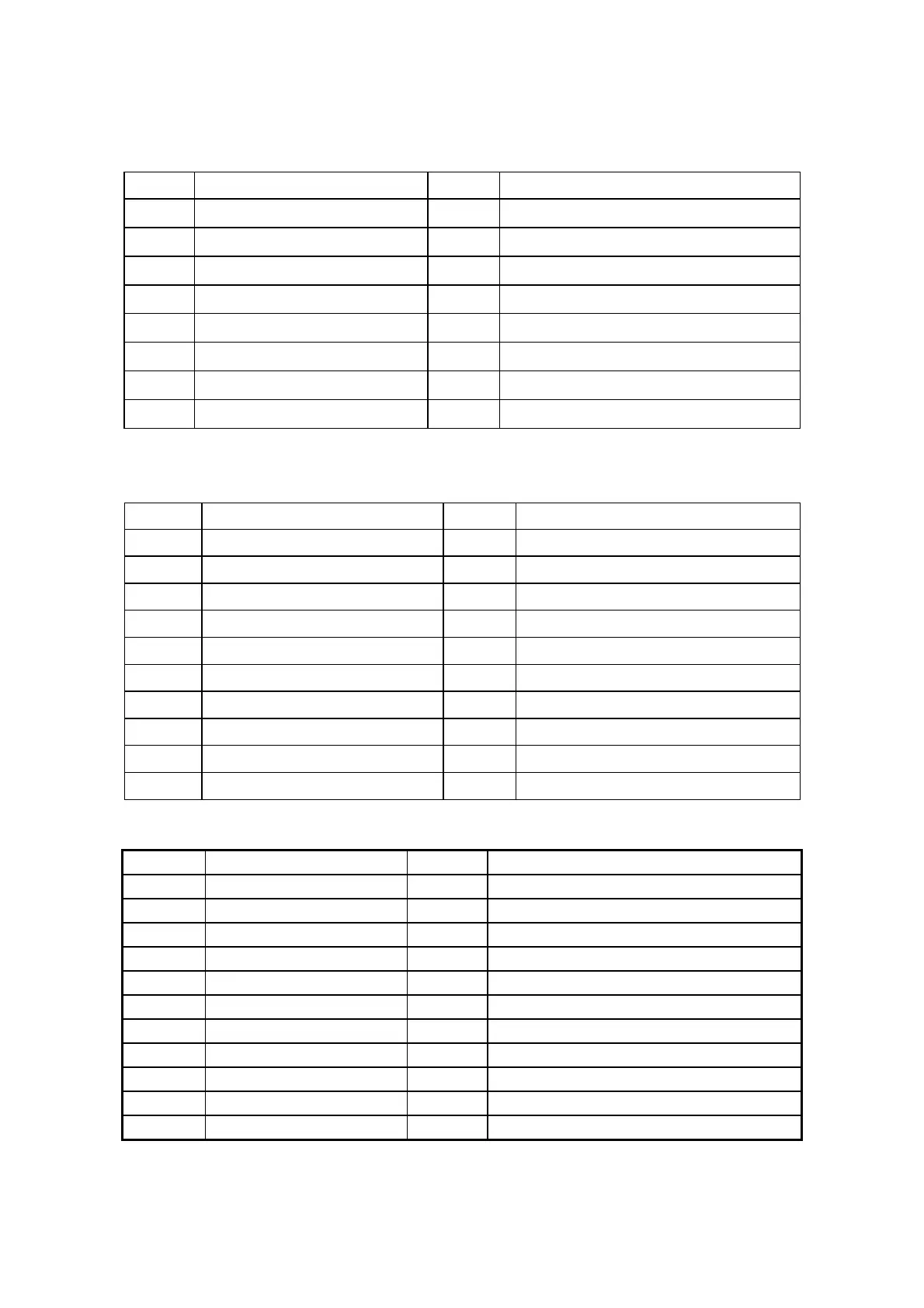
3. Input/Output Specification
3.1 Input Signal Connector
D-SUB
Pin No. Description Pin No. Description
1 Red 9 +5V (supply from PC)
2 Green 10 Sync GND
3 Blue 11 NC
4 NC 12 Bi-directional data (SDA)
5 GND 13 H-Sync
6 Red GND 14 V-sync (vclk)
7 Green GND 15 Data clock (SCL)
8 Blue GND
HDMI
Pin No. Description Pin No. Description
1
TMDS Data2+
11
TMDS Clock Shield
2
TMDS Data2 shield
12
TMDS Clock-
3
TDMS Data2-
13
CEC
4
TMDS Data1+
14
Reserved (N.C. on device)
5
TMDS Data1 shield
15
SCL
6
TMDS Data1-
16
SDA
7
TMDS Data0+
17
DDC/CEC Ground
8
TMDS Data0 shield
18
+5V Power
9
TMDS Data0-
19
Hot Plug Detect
10
TMDS Clock+
Full Scart
Pin No.
Signal
Pin No.
Signal
1
Audio output B ( right )
12
Comms data 1
2
Audio input B ( right )
13
Ground ( red )
3
Audio output A ( left )
14
Ground ( blanking )
4
Ground (audio )
15
Red input or Chroma
5
Ground ( blue )
16
RGB switching control
6
Audio input A ( left )
17
Ground ( video input & output )
7
Blue input
18
Ground ( RGB switching control )
8
Function select
19
Video output ( composite )
9
Ground ( green )
20
Sync or Video input ( composite or Y )
10
Comms data 2
21
Shield (Ground)
11
Green input
 Loading...