- 09 -
3-2-1 Function Description:
Main Board
Process signal which incept from exterior equipment then translate into signal that panel
can display.
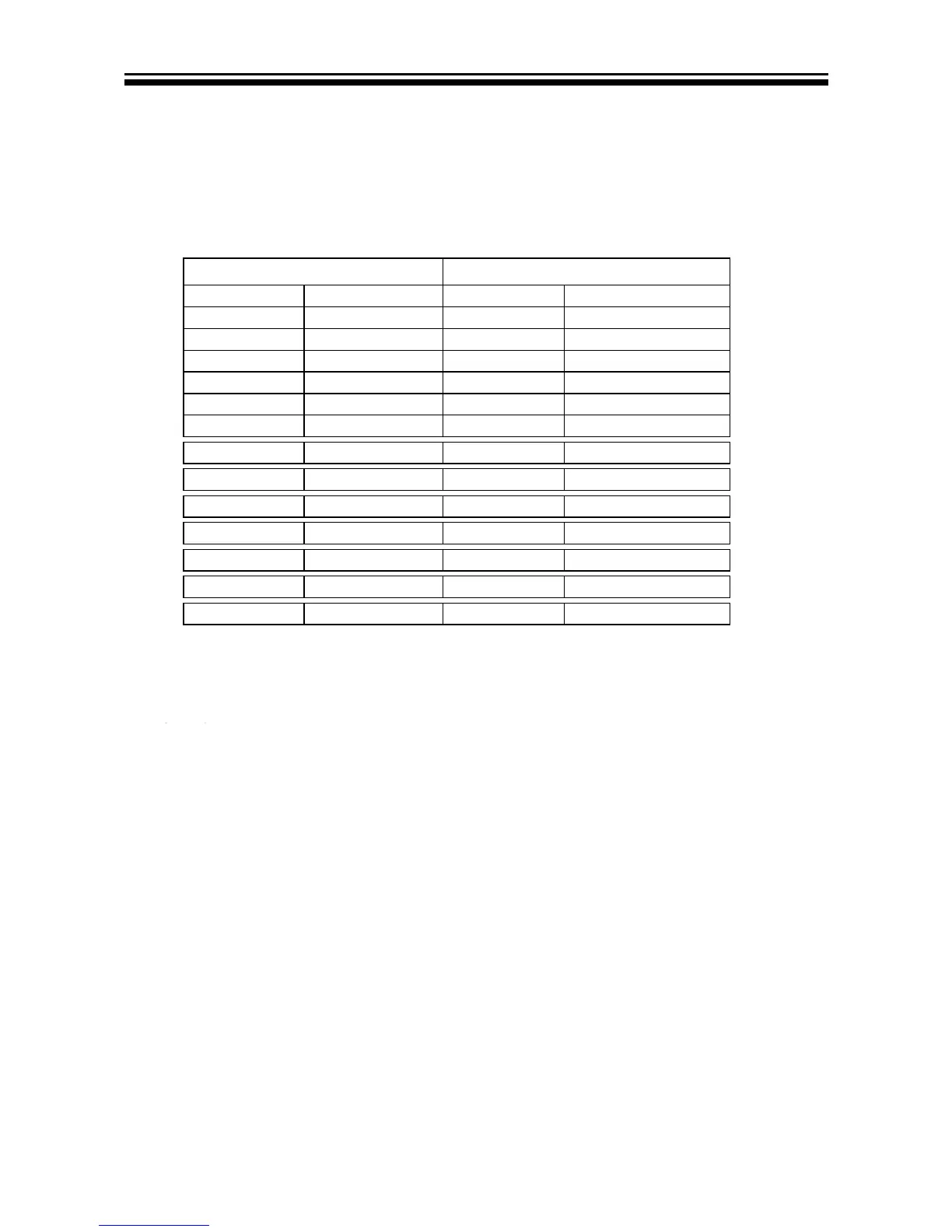
3-2-2 Connector defnition
Main board connector
Power connectors (J15ˈJ16)
J16
J15
Pin number Signal name Pin number Signal name
1 +5V 1 GND
GND
3 DIM 3 +5V
4
high voltage
4 +5V
5 POWER ON/OFF
6 +5VSTB
7 +5V
8 +5V
9 GND
10 GND
11 GND
12 +12V
13 +12V
Notes:
J16-Pin 2: Backlight on/off:
The system c an turn on or turn o ff t he backlight of TFT L CD P anel t hrough t he power
supply unit path.
CN115-Pin 5: System power on / standby
System board will use this pin to control system power.
J16-Pin 3: Control the luminance of backlight
The system can generate the P WM s ignal to control the strength of TFT LCD Panel’s
backlight through this connector
2
2
BL
J15
5
GND