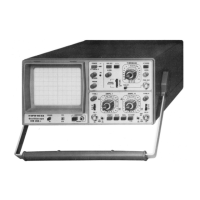
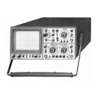
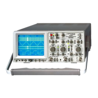
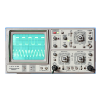
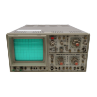
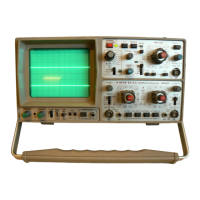
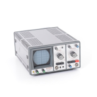
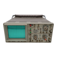
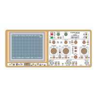
The HAMEG HM 205 is a 20 MHz dual-channel oscilloscope with digital storage capabilities, designed for general-purpose electronic measurements. It combines the functionality of a conventional analog oscilloscope with the advantages of digital storage, allowing for the capture and analysis of transient and repetitive signals.
Function Description
The HM 205 operates as a real-time oscilloscope for frequencies up to 20 MHz, providing two input channels (CH I and CH II) for simultaneous display of waveforms. In addition to real-time operation, it features a digital storage mode that allows for the acquisition, storage, and display of waveforms. This digital storage capability is particularly useful for observing single-shot events, very low-frequency signals, or comparing waveforms over time.
Key functions include:
- Dual-Channel Operation: Displays two independent input signals simultaneously, allowing for comparison and analysis of their phase and amplitude relationships.
- Digital Storage: Captures and stores waveforms in digital memory, enabling detailed analysis, pre-trigger viewing, and long-term observation of non-repetitive signals. The HM 205 can store up to two waveforms in its memory.
- Time Base: Offers a wide range of sweep speeds, from 0.5 µs/cm to 0.2 s/cm in real-time mode, and extended sweep speeds in digital storage mode for observing slow events.
- Vertical Amplifiers: Provides adjustable vertical sensitivity from 5 mV/cm to 20 V/cm, allowing for the measurement of a wide range of signal amplitudes.
- Triggering System: Features various trigger modes (Normal, Automatic, Single Sweep) and sources (CH I, CH II, External, Line) to stabilize repetitive waveforms and capture specific events. It also includes a TV-Sync-Separator for stable display of video signals.
- X-Y Operation: Allows for the display of one input signal against another, useful for phase measurements, Lissajous figures, and component testing.
- Component Tester: Integrates a basic component tester function, which displays characteristic curves of two-terminal and three-terminal components (resistors, capacitors, diodes, transistors) on the CRT, aiding in quick fault diagnosis.
- Graticule Illumination: Provides adjustable illumination of the CRT graticule for better visibility in various lighting conditions.
Important Technical Specifications
Oscilloscope Section:
- Bandwidth: 20 MHz (-3dB) for both CH I and CH II.
- Rise Time: Approximately 17.5 ns.
- Deflection Coefficients: 5 mV/cm to 20 V/cm in 1-2-5 sequence, with a variable control for continuous adjustment.
- Input Impedance: 1 MΩ || 30 pF.
- Input Coupling: AC, DC, GND.
- Max Input Voltage: 400 V (DC + Peak AC).
- Time Base Speeds: 0.5 µs/cm to 0.2 s/cm in 18 calibrated steps (1-2-5 sequence), with a variable control.
- Trigger Modes: Normal, Automatic, Single Sweep.
- Trigger Sources: CH I, CH II, External, Line.
- Trigger Coupling: AC, DC, LF (0.5 Hz), HF (50 kHz).
- X-Y Phase Shift: <3° from DC to 120 kHz.
Digital Storage Section:
- Bandwidth (Analog): 20 MHz.
- Bandwidth (Digital): 2 MHz.
- Sampling Rate: 10 MHz (real-time), 100 kHz (equivalent time).
- Memory Depth: 1024 x 8 bit per channel.
- Readout: 200 kHz.
- Display Modes: Refresh and Single (with Reset).
- Plotter Interface: (Optional).
Component Tester:
- Test Voltage: Max. 8.5 V (open circuit).
- Test Current: Max. 8 mA (short circuit).
- Test Frequency: 50 or 60 Hz (line frequency).
General Information:
- Cathode-Ray Tube: D14-364 P31/123, 8x10 cm graticule.
- Trace Rotation: Adjustable on front panel.
- Line Voltage: 110 V, 120 V, 220 V, 240 V selectable.
- Power Consumption: Approx. 42 W.
- Dimensions (W x H x D): 285 x 145 x 380 mm.
- Weight: Approx. 6.5 kg.
Usage Features
The HM 205 is designed for ease of use, with a logical layout of controls.
- Front Panel Controls: Clearly labeled knobs and pushbuttons for vertical, horizontal, and trigger settings. The digital storage functions are integrated into the existing control scheme, making it intuitive for users familiar with analog oscilloscopes.
- Display: The 8x10 cm CRT provides a clear display of waveforms. Graticule illumination enhances visibility, especially in low-light conditions.
- Probe Compensation: A dedicated CAL output (2 Vpp, 1 kHz square wave) is provided on the front panel for accurate compensation of oscilloscope probes, ensuring precise measurements.
- Tilt Handle: The instrument includes a tilt handle for adjusting the viewing angle, improving ergonomic comfort.
- Safety: The HM 205 is designed to meet safety standards (VDE 0871, Safety Class I), with protective earth grounding and insulated components. Users should always ensure proper grounding and avoid exceeding maximum input voltage ratings.
- Measurement Aids: The graticule provides divisions for easy amplitude and time measurements. The digital storage mode allows for cursor measurements and waveform comparisons, enhancing measurement accuracy.
- Triggering: The comprehensive triggering system, including TV-Sync-Separator, ensures stable displays of complex signals, including video waveforms. The HOLD-OFF control helps stabilize complex waveforms with multiple trigger points.
- Storage Operation: In storage mode, the HM 205 allows for pre-trigger viewing, enabling the capture of events that occur before the trigger point. This is crucial for analyzing transient phenomena. The HM 205 can store two waveforms, which can be compared or manipulated (e.g., sum, difference).
Maintenance Features
Regular maintenance ensures the longevity and accuracy of the HM 205.
- Cleaning: The instrument's exterior should be cleaned regularly with a soft, damp cloth. Avoid abrasive cleaners or solvents. The CRT screen can be cleaned with a soft, lint-free cloth.
- Calibration: Periodic calibration is recommended to maintain measurement accuracy. The manual provides detailed instructions for various adjustments, including astigmatism, symmetry, vertical amplifier gain, horizontal position, and trigger threshold. These adjustments typically require specialized test equipment.
- Component Replacement: The manual includes information on replacement parts and procedures for various components. For complex repairs, it is recommended to contact HAMEG service personnel or qualified technicians.
- Troubleshooting: A troubleshooting section in the manual helps diagnose common issues, such as no trace, unstable display, or incorrect measurements. This often involves checking power connections, control settings, and input signals.
- Environmental Conditions: The HM 205 is designed for indoor use within specific temperature and humidity ranges. Operating outside these conditions can affect performance and reliability. Proper storage in a dry, dust-free environment is important.
- Fuse Replacement: The instrument is protected by a mains/line voltage fuse. The manual specifies the correct fuse type and rating for different line voltages, emphasizing the importance of using only specified fuses to prevent damage and ensure safety.
- Service Information: The manual provides detailed instructions for internal adjustments and component replacement, including diagrams and test points. This information is valuable for qualified service technicians.
- Modular Design: The HM 205 utilizes a modular design, which simplifies maintenance and repair by allowing individual modules to be replaced or serviced. This can reduce downtime and repair costs.