Table of contents
Technical Data
....................
P
1
Accessories .....................
Z 1
Operating Instructions
General Information
...............
M 1
Use of tilt handle
.................
M 1
Safety.
......................
M 1
Operating conditions
................
M 2
Warranty
.....................
M 2
Maintenance
...................
M 2
Mains/Line voltage change
............
M 2
Type of Signal
...................
M 3
Amplitude Measurements
............
M 3
Time Measurements
...............
M 4
Connection of Test Signal
............
M 5
Operating
.....................
M 6
First Time Operation
...............
M 7
Trace Rotation TR
.................
M 7
DC Balance Adjustment
.............
M 7
Use and Compensation of Probes
........
M 8
Operating Modes of the Y Amplifier
.......
M 9
X-Y Operation
...................
Ml 0
X-Y Phase Measurements
............
Ml 0
Dual Trace Phase Difference Measurements
.
.
M 10
Measurement of an amplitude modulation
....
Ml 1
Triggering and
Timebase
.............
Ml 1
Triggering of video signals
............
Ml 2
Function of variable HOLD OFF control
......
Ml3
Sweep Delay /After Delay Triggeringe
......
Ml 3
Delay Mode Indication
..............
Ml 5
Component Tester
................
Ml 5
Miscellaneous
..................
Ml 7
Test Patterns
...................
Ml 8
Short Instruction
K
1.
Front Panel Elements
Folder with Front View
..............
K
2
Test Instructions
General
.......................
T 1
Cathode-Ray Tube: Brightness, Focus,
Linearity, Raster Distortions
.
T 1
Astigmatismus Check
...............
T 1
Symmetry and Drift of
thevertical
Amplifier
....
T 1
Calibration of the Vertical Amplifier
.........
T 1
Transmission Performance of the Vertical Amplifier
............................T2
Operating Modes: CH I/II-TRIG.
l/II,
DUAL, ADD,
CHOP., INV. l/II and XY-Betrieb
.
T 2
Triggering Checks
.................
T 3
Timebase
......................
T 3
SweepDelay
....................
T 4
Component
Tester
.................
T 4
Trace
Alignment
..................
T 4
Miscellaneous
...................
T 4
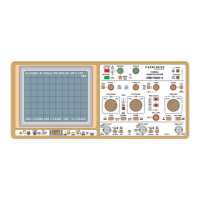
Oscilloscope
HM 604
Service Instructions
General .......................S 1
Instrument Case Removal ............. S 1
Operating Voltages ................. S 1
Minimum Brightness ................ S 1
Astigmatismus control ............... S 1
Trouble Shooting the Instrument .......... S 2
Replacement of Components and Parts ......S 2
Replacement of the Power Transformer ......S 2
Adjustments ....................S 3
Circuit Diagrams
Block Diagram
...................
D 1
Wiring Diagram
...................
D 2
Identification of Components
............
D 3
Y Input, Attenuator, Preamplifier CH.
l/II
......
D 4
Y intermediate Amplifiers, Trigger Pre-Amplifiers,
Component
Tester
................
D 5
Y Final Amplifier
..................
D 6
Post Trigger, Field Selector
.............
D 7
Timebase
(analog)
.................
D 8
Timebase
(digital)
..................
D 9
Tim,ebase Generator
................
DlO
X Final Amplifier, Calibrator
.............
Dl
1
CRT and HV circuit
.................
D12
Power Supply
....................
D13
Component Locations
XY Board
......................
D14
TB Board
......................
D15
PTFS Board
.....................
D16
TBG, CAL, YF Boards
................
D17
CO, EY, Z Boards
..................
D18
Subject to change without notice
9.88. 604