5.
Make the Electric
Connections
WARNING: To avoid possible electrical shock,
be sure electricity is turned off at the main fuse
box before wiring.
NOTE: This remote control unit is equipped
with 16 code combinations to prevent possible
interference from or to other remote units. The
frequency switches on your receiver and
transmitter have been preset at the factory.
Please recheck to make sure the switches on
transmitter and receiver are set to the same
position, any combination of settings will
operate the fan as long as the transmitter and
receiver are set to the same position.(Figure 9)
Step 1. (Figure 10) Insert the receiver into the
mounting bracket with the flat side of the
receiver facing the ceiling.
Step 2. (Figure 11) Motor to Receiver
Electrical Connections: Connect the black
wire from the fan to black wire marked "TO
MOTOR L". Connect the white wire from
the fan to the white wire marked "TO MOTOR
N" from the receiver. Connect the blue wire
from the fan to the blue wire marked "For
Light" from the receiver. Secure the wire
connections with the plastic wire nuts provided.
Step 3. (Figure 11) Receiver to House Supply
Wires Electrical Connections: Connect the
black (hot) wire from the ceiling to the black
wire marked "AC in L" from the receiver.
Connect the white(neutral) wire from the
ceiling to the white wire marked "AC in N"
from the Receiver. Secure the wire connections
with the plastic wire nuts provided.
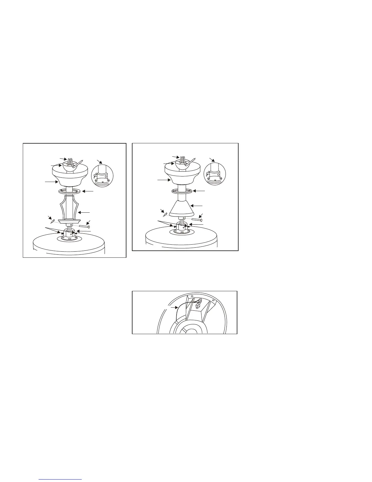
Figure 8
Safety Cable
INSTALLATION OF SAFETY SUPPORT
An additional safety support is provided to
prevent the fan from falling. Secure the
safety cable to the ceiling joist with screw
and washer, as illustrated in Figure 8.
Pin in
locked
position
Motor collar
Motor wires
Ball/downrod
assembly
Ceiling
canopy
Tighten
screws
firmly
Figure 7
Hanger pin
Locking pin
Decorative scroll
Canopy
cover
Pin in
locked
position
Motor collar
Motor wires
Ball/downrod
assembly
Ceiling
canopy
Tighten
screws
firmly
Figure 7A
Hanger pin
Locking pin
Collar cover
Canopy
cover
With 12" Downrod With 6" Downrod
Installing the fan without
decorative scroll (with 6" downrod)
(Recommend min. 8.25 ft. ceiling height)
1.Remove the hanger pin, lock pin and set
screws from the top of the motor
assembly.
2.Route wires exiting from the top of the
fan motor through the collar cover,
canopy cover, canopy and then through
the ball/downrod (Fig. 7A)
3.Follow the steps 7,8,9 in section titled
"Hanging the Fan" for installation.
 Loading...