4
8
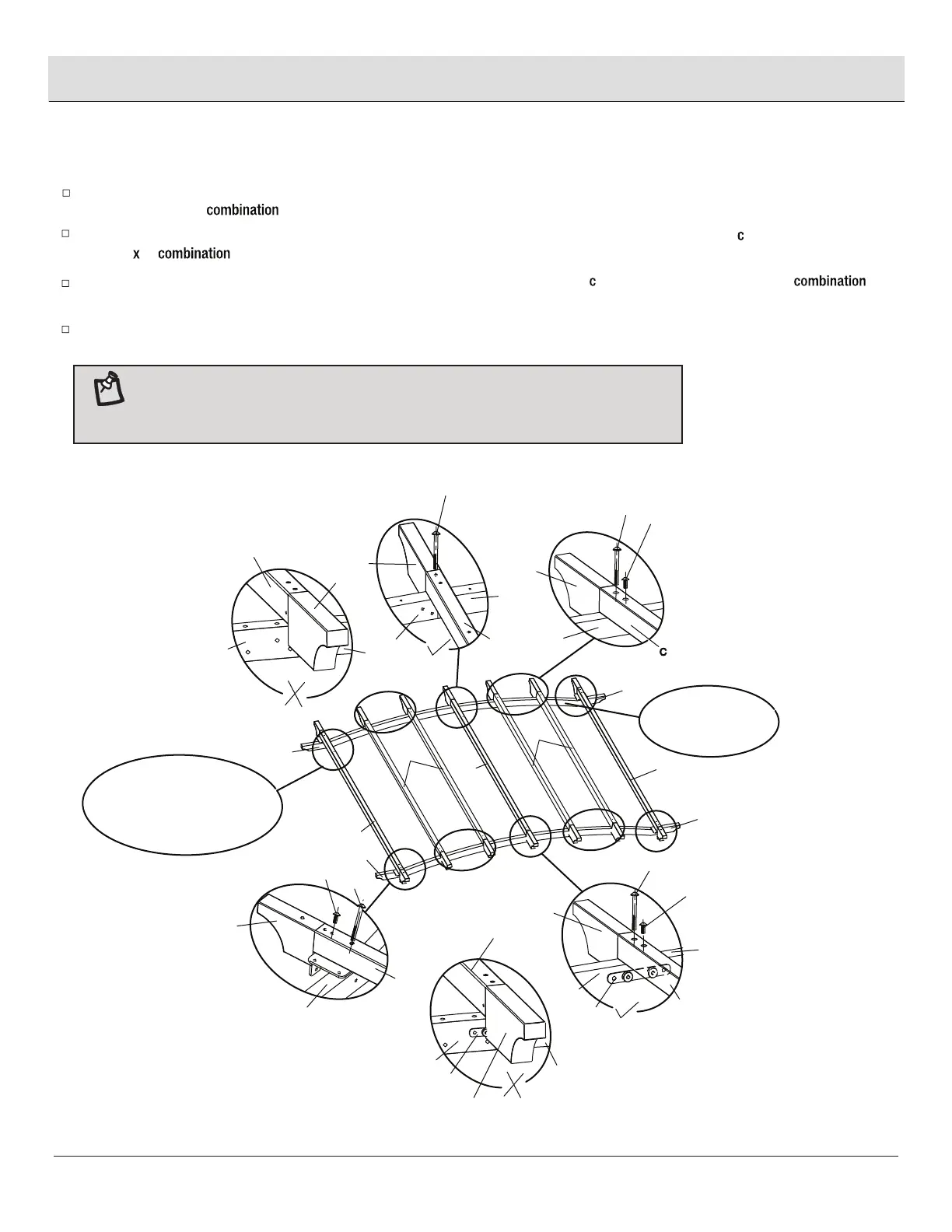
Assembly (continued)
Attaching the crossbars
Attach the center lengthways bar (E) with the upturned holes to the center of the connector bars (A & B) without the magnet iron
plate, using M6x80
bolts (DD).
Attach the lengthways bar (C) to the assembled connector bars (A & B) using M6x15 ombination bolts (AA) and M6x80 bolts (DD).
Repeat this step for the other three
lengthways bars (C) and the two side top bars (D).
Once all of the bolts are in place, fully tighten the bolts using the hex wrench (FF).
Attach the other side of the center lengthways bar (E) to the center of the connector bars (A & B) using M6x15
ombination bolts (AA)
and M6
80 bolts (DD).
Place the three upturned holes on the top bars (D) and the center lengthways bar (E) toward
the assembled connector bars (A & B) without magnet iron plate (K) to assemble the
protective cover (I) correctly.
NOTE :
C
D
D
C
C
E
A
B
A
AA
DD
A&B
S
DD
AA
E
A
B
K
Q
B
L
D
DD
AA
DD
A
E
Q
Q
B
A
E
Q
E
K
B
A
A&B
B
The upturned holes are to
lock the protective cover (I)
A&B without
magnet iron plate
 Loading...