9
SIZING
Determining dryer capacity at actual operating conditions
To determine the maximum inlet flow capacity of a dryer at
various operating conditions, multiply the rated capacity from
Table 1 by the multipliers shown in Table 2.
Example: How many scfm can an air-cooled model 1000
handle when compressed air to be dried is at 200 psig and
100°F; ambient air temperature is 80°F; and a 45°F dew point
temperature is desired?
Answer: 1,000 x 1.22 x 1.12 x 1.2 = 1,640 scfm.
TABLE 1
Rated capacity (scfm) and pressure drop @ 100 psig inlet
pressure, 100°F inlet temperature, and 100°F ambient tempera-
ture
MODEL 1000 1250 1500 1750 2000 2500 3000
Rated capacity 60 Hz 1000 1250 1500 1750 2000 2500 3000
of air-cooled 50 Hz 840 1050 1250 1460 1700 2100 2500
models (scfm)
INLET COMPRESSED AIR CONDITIONS
INLET INLET TEMPERATURES
PRESSURES 80°F 90°F 100°F 110°F 120°F
psig kgf/cm
2
27°C 32°C 38°C 43°C 49°C
50 3.5 1.35 1.05 0.84 0.69 0.56
80 5.6 1.50 1.17 0.95 0.79 0.66
100 7.0 1.55 1.23 1.00 0.82 0.70
125 8.8 1.63 1.31 1.07 0.91 0.74
150 10.5 1.70 1.37 1.13 0.95 0.80
175 12.3 1.75 1.42 1.18 0.99 0.84
200 14.0 1.80 1.47 1.22 1.03 0.89
TABLE 2
Air capacity correction factors (Multipliers)
COOLING MEDIUM*
AMBIENT
TEMPERATURE MULTIPLIER
°F °C
80 27 1.12
90 32 1.06
100 38 1.00
110 43 0.94
*Air-cooled models; water-cooled models use 1.15 multiplier if cooling water is
below 35°C, 95°F.
OUTLET DEWPOINT
DEWPOINT
TEMPERATURE MULTIPLIER
°F °C
38 3 1.0
45 7 1.2
50 10 1.3
1
5
2
6
1a
1b
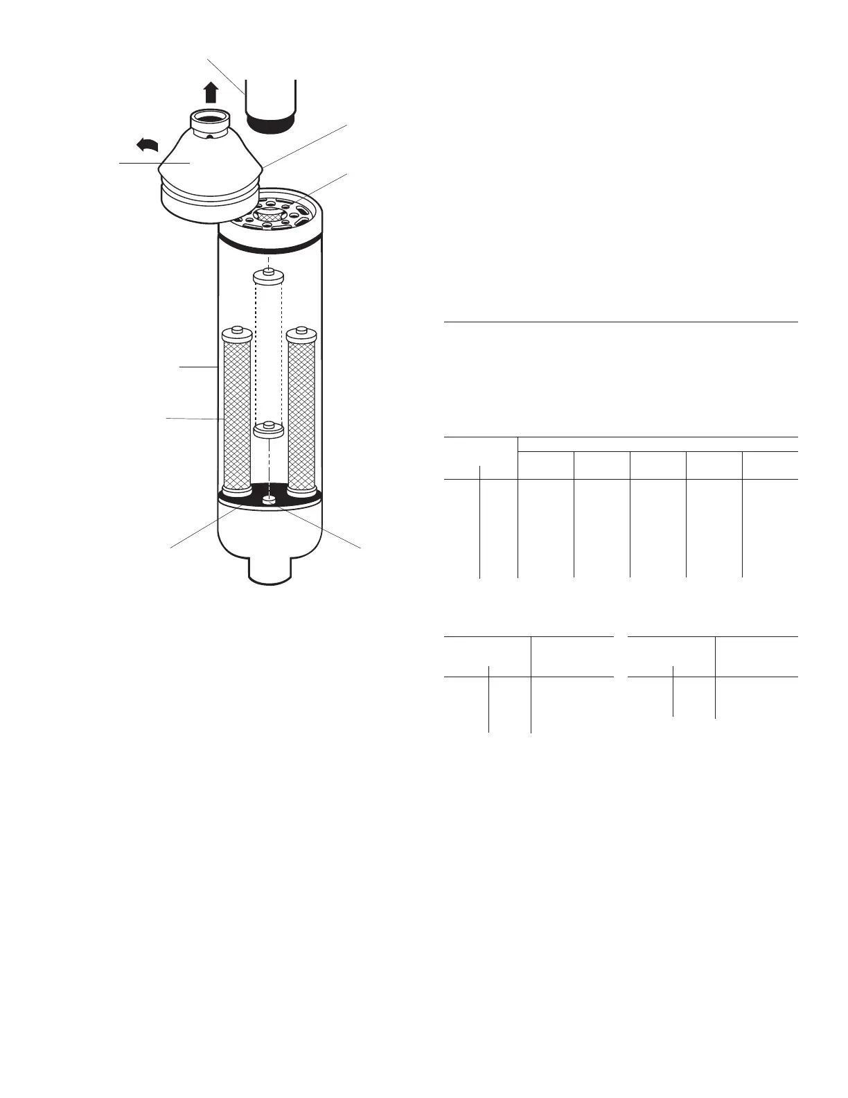
Upper
Shell Cap
Upper Piping
3.3 Check separator daily to be sure automatic drain
is discharging.
NOTE: Units with two stage filtration have two sets of drains.
3.4 Blow down separator weekly by pushing test button on
control panel.
3.5 Rebuild drain mechanism annually.
To facilitate service, maintenance kits are available.
 Loading...