3
IMPORTANT: READ PRIOR TO STARTING THIS EQUIPMENT
1.0 INSTALLATION
1.1 Location
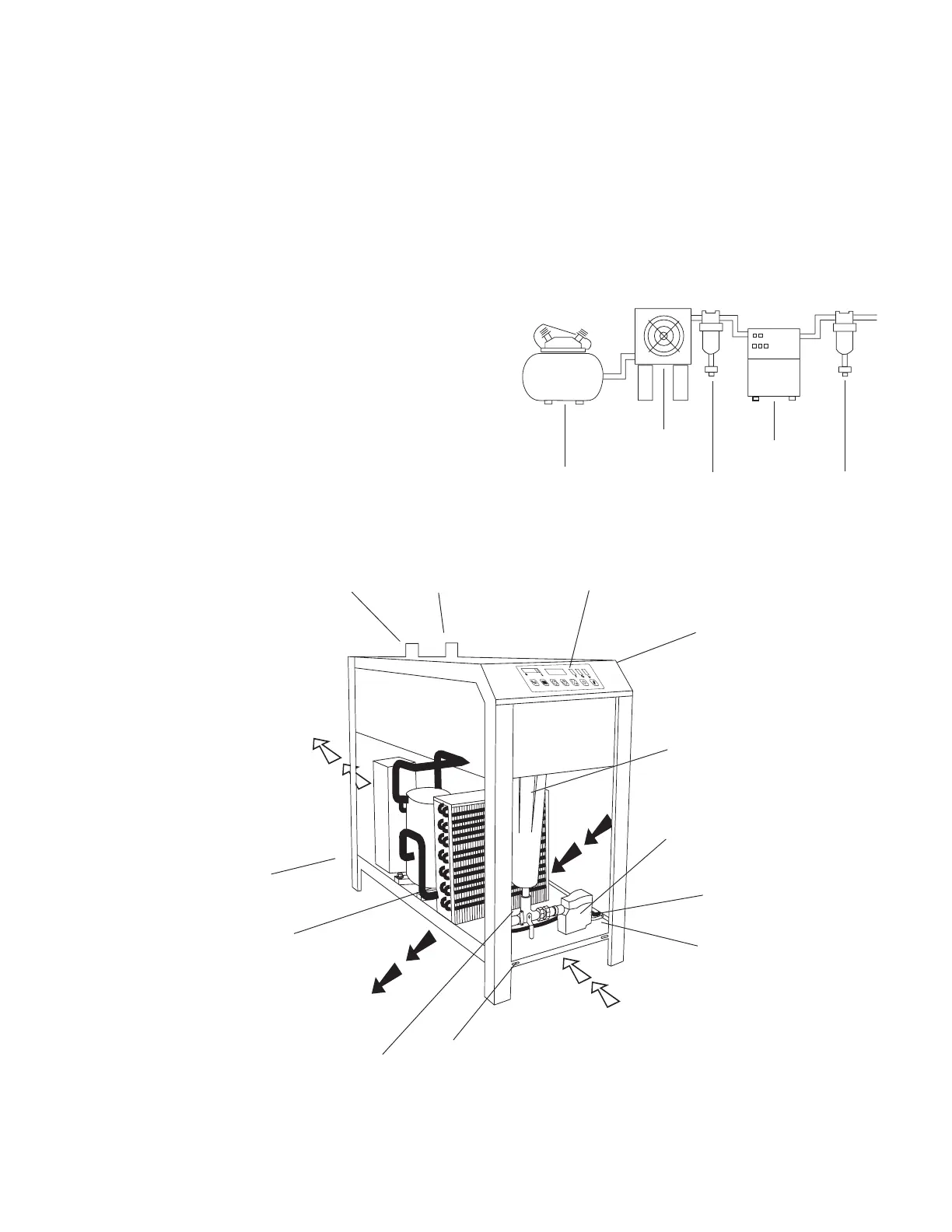
A. For typical placement in a compressed air system, see
drawing.
B. Air compressor intake – Locate air compressor so that
contaminants potentially harmful to the dryer (e.g.
ammonia) are not drawn into the air system.
C. Clearances Free air flow
Models 200 to 300
Front 24 inches (610 mm)
Back 12 inches (305 mm)
Sides 24 inches (610 mm)
Models 400 and 500
Front 12 inches (305 mm)
Back 12 inches (305 mm)
Sides 36 inches (915 mm)
Service - To facilitate maintenance leave 24 inches
(610 mm) of clearance in front of dryer.
D. Standard units are designed to operate in ambients:
Air-cooled: 45 to 110°F (7 to 43°C).
Water-cooled: 45 to 130°F (7 to 54°C).
E. Installations in altitudes above 4500 feet (1370 meters) –
Dryer is adjusted to operate in altitudes up to 4500 feet
(1370 meters). If dryer is installed in an altitude above
this, and has not been preset at the factory for this
altitude, contact manufacturer’s Service Department.
F. The installation of a flexible connection prior to the dryer is
recommended to prevent possible damage from vibration.
NOTE: Outdoor installation – Standard units are designed for
indoor installation. Contact manufacturer if installing outdoors.
Aftercooler
Separator
Dryer
Oil Removal
Filter
Compressor
33F..............39F
1C.............. 4C
Air Outlet
Air Inlet
Control
Panel
Moisture
Separator
Electrical Demand
Drain (EDD)
Automatic
Drain Outlet
Condenser
Electrical
Entry
Service Panel
Quick Release
Locks
Ambient Air Flow from
front to back on Models
200, 250, 300
RS232
Port
Petcock and
Manual Drain Outlet
3-way valve for
Manual Draining
Ambient Air Flow from right
to left on Models 400, 500
 Loading...