4
Refer to Serial Number Tag for maximum
working pressure. Do not exceed dryer’s Maximum Working
Pressure.
NOTE: Install dryer in air system at highest pressure possible
(e.g. before pressure reducing valves).
NOTE: Install dryer at coolest compressed air temperature
possible. Maximum inlet compressed air temperature: 120°F
(49°C). If inlet air exceeds this temperature, precool the air
with an aftercooler.
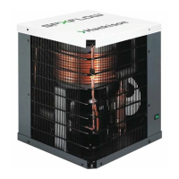
B. Air Outlet – Connect air outlet to downstream air lines.
C. Bypass piping – If servicing the dryer without interrupting
the air supply is desired, piping should include inlet and
outlet valves and an air bypass valve.
D. Water cooled models – cooling water inlet and outlet
1. Connect cooling water supply to cooling water inlet.
2. Connect cooling water return line to cooling water
outlet connection.
NOTE: Strainer and water regulating valve are supplied on
water cooled models.
1.4 Electrical connections
IMPORTANT: Use copper supply wires only.
A. Dryer is designed to operate on the voltage, phase, and
frequency listed on the serial number tag.
B. Connect power source to terminal strip in electrical
enclosure.
NOTE: Refrigeration condensing unit is
designed to run continuously and should
NOT
be wired to cycle on/off with the air compressor.
1.5 Moisture separator
A. An automatic electric demand drain (EDD)
discharges condensate removed by the
separator. It may be desirable to pipe the
condensate from the EDD outlet to a
suitable drain.
B. For manual draining, convenient dryer depressurization,
and EDD service, a three-way valve at the bottom of the
moisture separator and before the EDD is installed. For
manual draining, turn the valve handle so it is in a
horizontal position. Open the petcock on the side of the
dryer base pan to discharge the condensate or to depres-
surize the dryer if it has been bypassed. The petcock can
be left in a throttled (partially opened) position should
there be a problem with EDD.
NOTE: Discharge is at system pressure. Drain line should be
anchored.
NOTE: Condensate may contain oil. Comply with applicable
laws concerning proper disposal.
1.6 Electronic Demand Drain
Installation
1. Remove Service Panel by removing two shipping screws
and turning (2) Quick Release Locks.
2. Reach inside and remove screws on Separator/filter
shipping support bracket and remove bracket.
3. Reach behind filter and cut plastic shipping strap holding
Energy Saving Demand Drain.
4. Insert Demand Drain into brass quick disconnect on
bottom of Separator/filter.
5. Remove manual petcock from drain hose and mount into
manual outlet drain connection on outside of side panel.
Operation
A. Verify that isolation valves are open. If the drain fails to
discharge after the valve is energized, the electronic control
circuit will repeatedly energize the valve in an attempt to
clear the discharge port. If, after 60 seconds, the drain still
fails to discharge, the control circuit then switches to the
alarm mode. In this mode the valve is de-energized and
the red alarm light is activated on the drain and the dryer
controller. The valve is then automatically energized every
4 minutes for 5 seconds. Check the drain operation. Push
drain (push-to-test) button on the Energy Management
Monitor control board to energize drain. A flow of conden-
sate and/or air should be present at the drain outlet. The
alarm mode automatically clears after the drain returns to
normal operation.
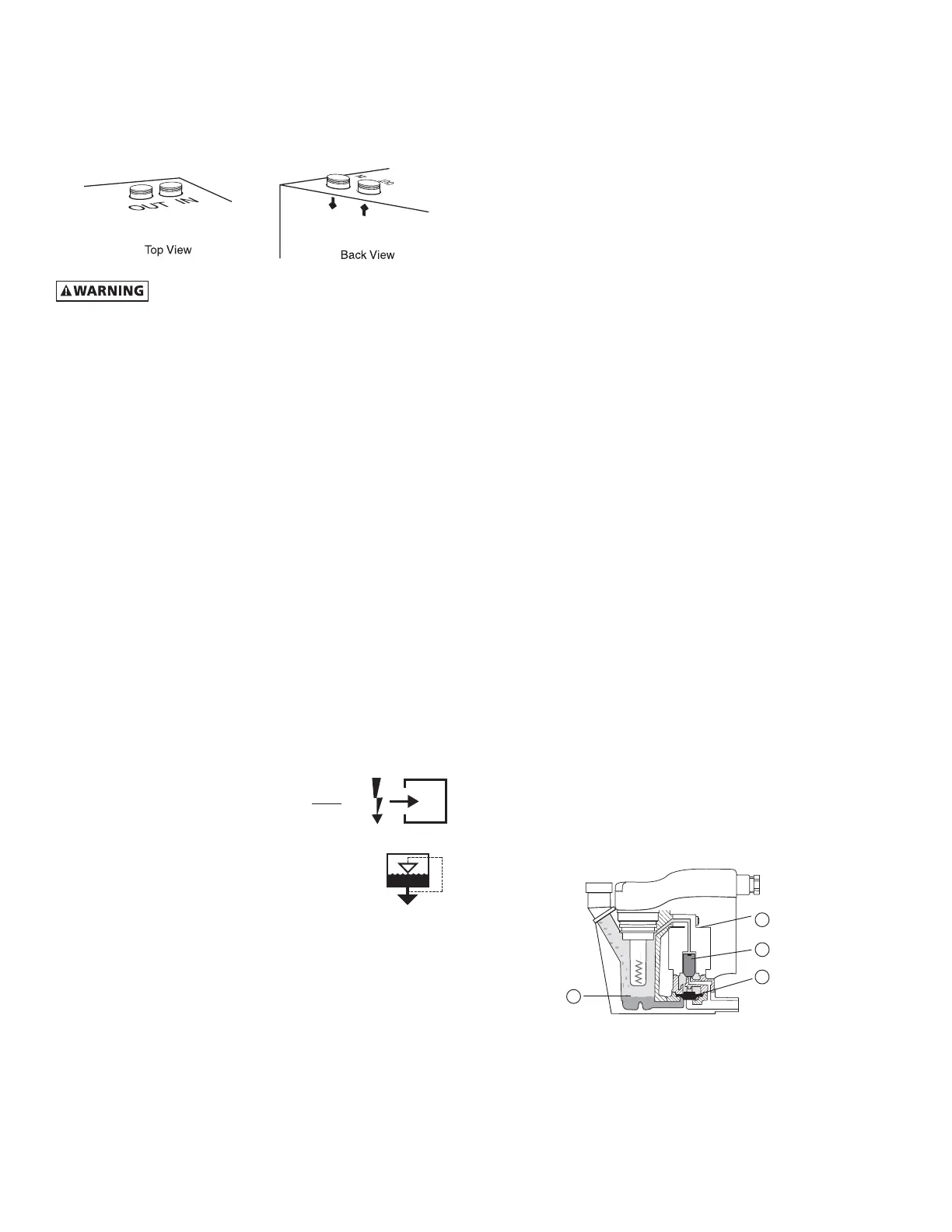
B. Condensate enters the reservoir (1) through the inlet port.
When the condensate level in the reservoir covers the
capacitance sensor, an electronic signal is sent to the solid
state countdown processor. The processor delays the
opening of the solenoid valve for a given period of time.
Once the time has elapsed, the solid state processor
transmits information to energize the coil in the solenoid
valve (2). The magnetic force of the coil causes the
solenoid core (3) to move, closing the pilot air supply line
and opening the pilot air exhaust line. After the pilot air
above the diaphragm (4) is vented, pressure in the reser-
voir opens the discharge port and forces the condensate
through the discharge port and outlet piping.
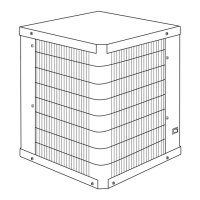
1.2 Mounting
Mount on floor or shelf free from vibration.
1.3 Piping connections
A. Air Inlet - Connect compressed air line from air source to
air inlet.
1
2
3
4
 Loading...