2
IMPORTANT: READ PRIOR TO STARTING THIS EQUIPMENT
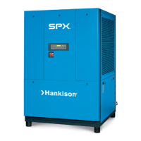
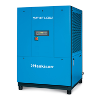
1.0 INSTALLATION
1.1 Location
A. For typical placement in a compressed air system, see draw-
ing.
B. Air compressor intake – Locate air compressor so that con-
taminants potentially harmful to the dryer (e.g. ammonia) are
not drawn into the air system.
C. Dryer should be installed in a moderately heated, well ven-
tilated area. Avoid locations immediately adjacent to cold
exterior windows or walls, or adjacent to high temperature
ovens or boilers.
D. Clearances:Freeairow
Front 37.3/8 inches (950 mm)
Back 37.3/8 inches (950 mm)
Left Side 37.3/8 inches (950 mm)
Right Side 6 inches (153 mm)
Top 25.5/8 inches (650 mm)
Service - To facilitate maintenance leave 37.3/8 inches (950
mm) of clearance in front of dryer.
E. Standard units are designed to operate in ambients:
Air-cooled: 40 to 110°F (4 to 43°C).
Water-cooled: 40 to 130°F (4 to 54°C).
F. Dryer is designed to operate at all altitudes - no adjustment
for altitude is required.
G. Theinstallationofaexibleconnectionpriortothedryeris
recommended to prevent possible damage from vibration.
NOTE: Outdoor installation – Standard units are designed for
in door installation. Contact manufacturer if installing outdoors.
Aftercooler
Separator
Dryer
Compressor
COOLING WATER
INLET
COOLING WATER
OUTLET
COOLING WATER
OUTLET
COOLING WATER
INLET
DETAIL ‘A’
Cooling Water Connection Ports for
Models 800, 1000, 1250, 1500
DETAIL ‘B’
Cooling Water Connection Ports for
Models 1750, 2000, 2500, 3000
COOLING AIR FLOW
COOLING AIR FLOW
CONDENSATE DRAIN
(OPTIONAL)
CONDENSATE DRAIN
CONDENSATE DRAIN
LEFT SIDE VIEW
CONTROL PANEL
FRONT SIDE VIEW
SEE DETAILS ‘A’ AND ‘B’
FOR WATER CONNECTION
PORT IDENTIFICATION
 Loading...